STOP AND START SYSTEM, Diagnostic DTC:B22C0
| DTC Code | DTC Name |
|---|---|
| B22C0 | BBC Overcurrent |
DESCRIPTION
A backup boost converter is built into the engine stop and start ECU.
The backup boost converter helps maintain battery voltage to prevent various functions from failing if power source voltage supplied from the backup boost converter drops due to the high electrical load when the engine is restarted by stop and start control.
The backup boost converter helps maintain the power source voltage if the battery voltage drops due to the high electrical load when the engine is restarted by stop and start control.
Tech Tips
A relay function and fuse function are provided in the backup boost converter.
If there is a malfunction in any of the electrical system circuits connected to the backup boost converter, the fuse and relay functions shut off the malfunctioning circuit to protect other circuits (remains shut off until next trip).
When the electrical system circuit is shut off, power to the circuit is cut off, causing any systems connected to the circuit to be disabled.
The fuse function is reset* when the ignition switch is turned off. If the malfunction still exists in the electrical system circuit that has been shut off by the relay function, it will be shut off again by the relay and fuse functions the next time the ignition switch is turned to ON.
*: A semiconductor fuse self-resets according to electric signals.
-
Radio and display receiver assembly
-
Air conditioning control assembly
-
Skid control ECU (brake actuator assembly)
-
Spiral with sensor cable sub-assembly
-
Combination meter assembly
-
Millimeter wave radar sensor assembly
-
Forward recognition camera
-
Body ECU
The backup boost converter supplies power to:
| DTC No. | Detection Item | DTC Detection Condition | Trouble Area | Warning Indicate | Memory |
|---|---|---|---|---|---|
| B22C0 | BBC Overcurrent | The following condition continues for 1 second or more (1 trip detection logic):
|
|
Blinks | DTC stored |
CONFIRMATION DRIVING PATTERN
Tech Tips
DTCs for the stop and start system are not cleared even if the malfunction has been repaired. After repairing the malfunction, be sure to clear the DTCs.
-
Tech Tips
-
If the cable is disconnected from the battery terminal, stop and start control is prohibited until refresh charge is completed.
In this case, let the vehicle idle with the battery temperature at 11°C (51°F) or higher for 5 to 60 minutes to complete the refresh charge. (The refresh charge is complete when the Data List item Status of Battery Charge Control changes from "Refresh Charge Mode".)
-
If the GTS is not available and the Data List item Status of Battery Charge Control cannot be checked, charge the battery by idling the engine for approximately 5 to 60 minutes or driving the vehicle, and then drive the vehicle and check that stop and start control operates.
If the engine is started with the hood open, the system determines that a jump start has occurred. Therefore, make sure that the hood is closed before starting the engine and driving the vehicle.
-
After the refresh charge completes, turn the engine switch off, wait for at least 30 seconds, and then start the engine again.
If the vehicle enters refresh charge mode again while the engine is idling, the initial refresh charge did not properly complete, so wait for the refresh charge to complete.
-
Allow the engine to idle for 3 minutes after the engine warms up and check that the engine speed is within 50 rpm of the target idle speed.
CONFIRMATION AFTER TROUBLESHOOTING
-
Connect the GTS to the DLC3.
-
Turn the ignition switch to ON and turn the GTS on.
-
Clear the DTCs.
Powertrain > Stop and Start > Clear DTCs -
Start the engine and warm it up.
-
Drive the vehicle at 7 km/h (4.3 mph) or more.
CAUTION:
When performing Confirmation Driving Pattern, obey all speed limits and traffic laws.
-
for Automatic Transmission:
Depress the brake pedal and stop the vehicle.
for Manual Transmission:
Stop the vehicle, move the shift lever to neutral and release the clutch pedal.
-
Keep the engine stopped by stop and start control for 1 second or more. (for Automatic Transmission: Keep the shift lever in D.)
-
for Automatic Transmission:
Release the brake pedal with the shift lever in D to start the engine.
for Manual Transmission:
Depress the clutch pedal and start the engine.
Tech Tips
If the engine cranks slowly when the engine is restarted, it can be determined that the battery voltage is low.
-
Check that DTCs are not output.
Powertrain > Stop and Start > Trouble Codes
-
-
Tech Tips
-
If the cable is disconnected from the battery terminal, stop and start control is prohibited until refresh charge is completed.
In this case, let the vehicle idle with the battery temperature at 11°C (51°F) or higher for 5 to 60 minutes to complete the refresh charge. (The refresh charge is complete when the Data List item Status of Battery Charge Control changes from "Refresh Charge Mode".)
-
If the GTS is not available and the Data List item Status of Battery Charge Control cannot be checked, charge the battery by idling the engine for approximately 5 to 60 minutes or driving the vehicle, and then drive the vehicle and check that stop and start control operates.
If the engine is started with the hood open, the system determines that a jump start has occurred. Therefore, make sure that the hood is closed before starting the engine and driving the vehicle.
-
After the refresh charge completes, turn the engine switch off, wait for at least 30 seconds, and then start the engine again.
If the vehicle enters refresh charge mode again while the engine is idling, the initial refresh charge did not properly complete, so wait for the refresh charge to complete.
STOP AND START SYSTEM OPERATION CHECK
-
Start the engine and warm it up.
-
Turn the air conditioning system off.
-
Drive the vehicle at 7 km/h (4.3 mph) or more.
CAUTION:
When performing Confirmation Driving Pattern, obey all speed limits and traffic laws.
-
for Automatic Transmission:
Depress the brake pedal and stop the vehicle.
for Manual Transmission:
Stop the vehicle, move the shift lever to neutral and release the clutch pedal.
-
Allow the engine to stop by stop and start control. (for Automatic Transmission: Keep the shift lever in D.)
-
for Automatic Transmission:
Release the brake pedal with the shift lever in D to start the engine.
for Manual Transmission:
Depress the clutch pedal and start the engine.
-
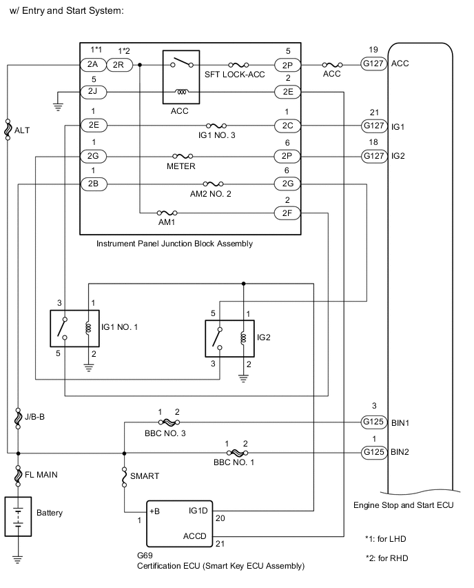
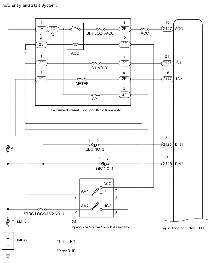
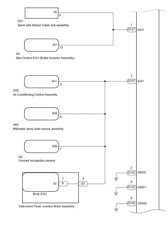
WIRING DIAGRAM
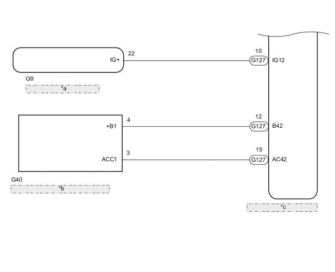
| *a | Combination Meter Assembly |
| *b | Radio and Display Receiver Assembly |
| *c | Engine Stop and Start ECU |
CAUTION / NOTICE / HINT
Note
-
Before replacing the engine stop and start ECU, read the number of starter operations and total number of engine starts and write it into a new engine stop and start ECU.
-
After replacing the engine stop and start ECU or air conditioning amplifier assembly, reset and perform learning of the air conditioning information in the engine stop and start ECU.
-
After replacing the engine stop and start ECU or airbag sensor assembly, perform deceleration sensor zero point clear and calibration
-
for Automatic Transmission:
When the engine stop and start ECU is replaced, check the electromagnetic oil pump.
-
Inspect the fuses for circuits related to this system before performing the following procedure.
Tech Tips
-
Using the GTS, read the freeze frame data before troubleshooting. System condition information is recorded as freeze frame data the moment a DTC is stored. This information can be useful when troubleshooting.
-
If electrical load from additional devices installed on the vehicle (aftermarket audio system, etc.) is applied to the B42 or IG41 terminal in the engine stop and start ECU, the fuse function of the backup boost converter may operate.
If the fuse function of the backup boost converter operates, any systems connected to the B42 or IG41 terminal in the engine stop and start ECU will not operate.
PROCEDURE
-
CHECK HARNESS AND CONNECTOR (ENGINE STOP AND START ECU - BBC FUSE)
-
Disconnect the G125 engine stop and start ECU connector.
-
Remove the BBC NO. 1 and BBC NO. 3 fuses from the engine room relay block and junction block.
-
Measure the resistance according to the value(s) in the table below.
Standard Resistance Tester Connection Condition Specified Condition G125-1 (BIN2) - BBC NO. 1 fuse terminal 2 Always Below 1 Ω G125-3 (BIN1) - BBC NO. 3 fuse terminal 2 Always Below 1 Ω G125-1 (BIN2) - Body ground Always 10 kΩ or higher G125-3 (BIN1) - Body ground Always 10 kΩ or higher BBC NO. 1 fuse terminal 2 - Body ground Always 10 kΩ or higher BBC NO. 3 fuse terminal 2 - Body ground Always 10 kΩ or higher Result Proceed to OK NG
NG 
REPAIR OR REPLACE HARNESS OR CONNECTOR
OK 
-
-
CHECK HARNESS AND CONNECTOR (ENGINE STOP AND START ECU - EACH ECU OR SENSOR)
-
Disconnect the G127 engine stop and start ECU connector.
-
Disconnect the G40 radio and display receiver assembly connector.
-
Disconnect the G32 air conditioning control assembly connector.
-
Disconnect the A64 millimeter wave radar sensor assembly connector.
-
Disconnect the Q4 forward recognition camera connector.
-
Disconnect the 2D instrument panel junction block assembly connector.
-
Measure the resistance according to the value(s) in the table below.
Standard Resistance Tester Connection Condition Specified Condition G127-12 (B42) - G40-4 (+B1) Always Below 1 Ω G127-3 (IG41) - G32-2 (IG+) Always Below 1 Ω G127-3 (IG41) - A64-8 (IGB) Always Below 1 Ω G127-3 (IG41) - Q4-7 (IGB) Always Below 1 Ω G127-3 (IG41) - 2D-5 Always Below 1 Ω G127-12 (B42) - Body ground Always 10 kΩ or higher G127-3 (IG41) - Body ground Always 10 kΩ or higher Result Proceed to OK NG
NG
REPAIR OR REPLACE HARNESS OR CONNECTOR
OK
-
-
CHECK ENGINE STOP AND START ECU
-
Disconnect the engine stop and start ECU connector.
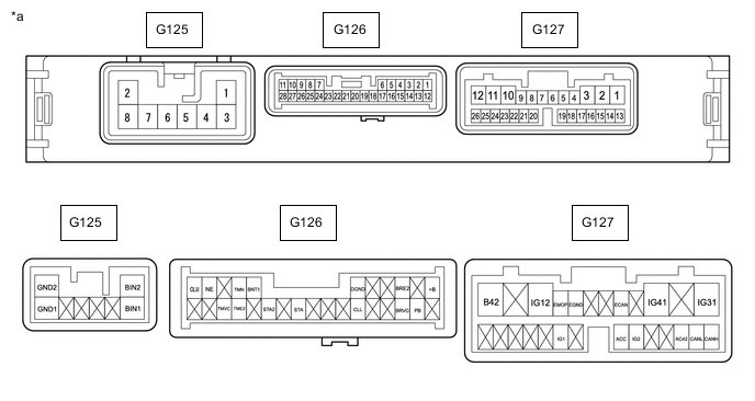
*a Component without harness connected
(Engine Stop and Start ECU)
- - -
Measure the resistance according to the value(s) in the table below.
Standard Resistance Tester Connection Condition Specified Condition G127-12 (B42) - G126-6 (DGND) Always 10 kΩ or higher G127-3 (IG41) - G126-6 (DGND) Always 10 kΩ or higher Result Proceed to OK NG
NG
REPLACE ENGINE STOP AND START ECU Click here
OK
-
-
CHECK VEHICLE CONDITION (B42, IG41 CIRCUIT)
-
Check that additional devices installed to the vehicle (aftermarket audio system, etc.) are not connected to the B42 or IG41 terminal circuit in the engine stop and start ECU.
Result Result Proceed to Load from an additional device installed to the vehicle (aftermarket audio system, etc.) is not applied. A Load from an additional device installed to the vehicle (aftermarket audio system, etc.) is applied. B
A
GO TO TROUBLE AREAS (TROUBLESHOOTING PROCEDURE FOR ECUS CONNECTED TO B42 AND IG41 TERMINALS)
B
END (REMOVE ELECTRICAL LOAD FROM ADDITIONAL DEVICE)
-