TOYOTA PARKING ASSIST-SENSOR SYSTEM OPERATION CHECK
CHECK INITIAL CHECK FUNCTION
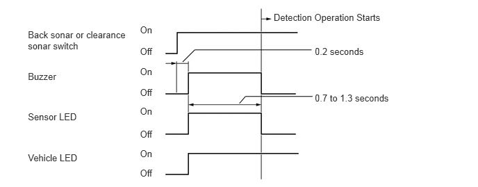
Check the initial check function for the buzzer.
When the back sonar or clearance sonar switch assembly is turned on, check that the following occurs: 1) after 0.2 seconds, the buzzer sounds for approximately 0.7 to 1.3 seconds, and 2) the system starts the obstacle detection operation.
Check the initial check function for the indicator.
When the back sonar or clearance sonar switch assembly is turned on, check that the following occurs: 1) after 0.2 seconds, the sensor LED illuminates for approximately 0.7 to 1.3 seconds, and 2) the system starts the obstacle detection operation.
After the back sonar or clearance sonar switch assembly is turned on, check that the vehicle LED illuminates.
Check the initial check function for the sensor.
Approximately 0.2 seconds after the ignition switch is turned to ON and the back sonar or clearance sonar switch is turned on, all the sensors are checked by the system.
When the shift lever is operated, the system starts the obstacle detection operation.
MALFUNCTION INDICATOR AND BUZZER
Open circuit indication
If there is an open circuit between the ultrasonic sensor and the clearance warning ECU, or a sensor is malfunctioning, the malfunction is displayed as shown in the illustration.
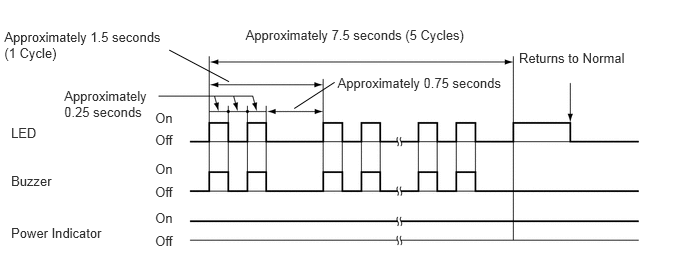 Tip:
Tip:The example shows an open circuit in the ultrasonic sensor (front left sensor).
Troubleshoot according to each inspection procedure (Click here).
Frozen indication
If a sensor is covered with foreign matter, such as mud or snow, the affected sensor is displayed as shown in the illustration.
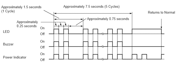 Tip:
Tip:The example shows that the ultrasonic sensor (front left sensor) is covered with foreign matter.
Troubleshoot according to each inspection procedure (Click here).
DETECTION RANGE MEASUREMENT AND INDICATOR CHECK
CAUTION:Apply the parking brake securely so that the vehicle does not move.
Turn the ignition switch to ON.
Turn the back sonar or clearance sonar switch on.
Move the shift lever to R to check the rear corner sensors and rear center sensors.
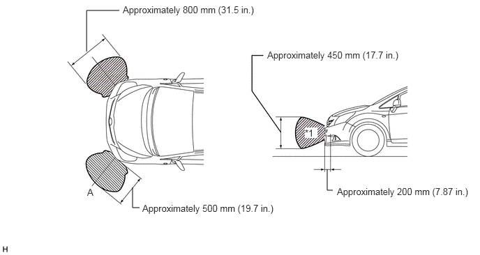
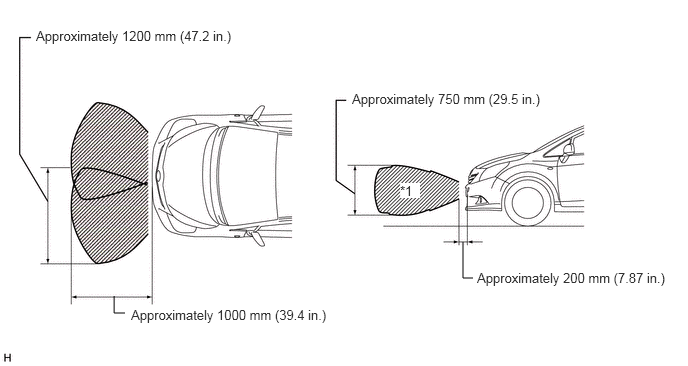
Move a pole around the sensor to measure the detection range of the sensor.
Note:These detection ranges are applicable when positioning a pole with a diameter of φ60 mm (2.36 in.) parallel or perpendicular to the ground.
The ranges vary depending on the measuring method and type of obstacle (such as walls).
For close-range and medium-range detection, the values shown are for when using a pole with a diameter of φ60 mm (2.36 in.). For long-range detection, the values shown are for when using walls.
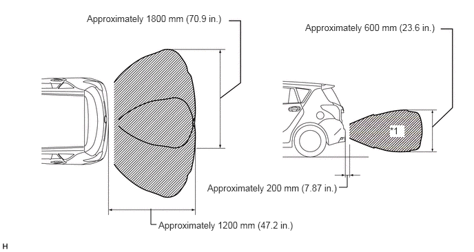
The No. 1 ultrasonic sensor side view detection range hatched area*1 represents the cross section of the top view of the detection range along the lines labeled A. The hatched area*1 does not represent the entire side view detection range.
Front corner sensor detection range
Front center sensor detection range
Rear corner sensor detection range

Rear center sensor detection range
When the ultrasonic sensors detect an obstacle with the back sonar or clearance sonar switch on, check that the buzzer sounds.
Table 1. Operation Condition Shift Lever Position
Vehicle Speed
Buzzer Detection, Accessory Meter Detection
Front Corner LH
Front Corner RH
Front Center LH
Front Center RH
Rear Corner LH
Rear Corner RH
Rear Center LH
Rear Center RH
except P*, R
10 km/h (6.2 mph) or less
○
○
X
X
R
No Limit
○
X
○
○
*: except Manual Transaxle
Check that the buzzer sounds with the back sonar or clearance sonar switch on.
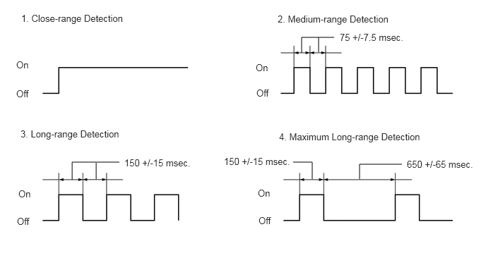
Table 2. Front Corner Detection Range Detection
Distance
1. Close-range detection
Within 250 +/-50 mm (9.84 +/-1.97 in.)
2. Medium-range detection
250 +/-50 to 375 +/-50 mm (9.84 +/-1.97 to 14.8 +/-1.97 in.)
3. Long-range detection
375 +/-50 to 500 +/-50 mm (14.8 +/-1.97 to 19.7 +/-1.97 in.)
Table 3. Front Center Detection Range Detection
Distance
1. Close-range detection
Within 300 +/-50 mm (11.8 +/-1.97 in.)
2. Medium-range detection
300 +/-50 to 375 +/-50 mm (11.8 +/-1.97 to 14.8 +/-1.97 in.)
3. Long-range detection
375 +/-50 to 500 +/-60 mm (14.8 +/-1.97 to 19.7 +/-2.36 in.)
4. Maximum long-range detection
500 +/-60 to 1000 +/-150 mm (19.7 +/-2.36 to 39.4+/-5.91 in.)
Table 4. Rear Corner Detection Range Detection
Distance
1. Close-range detection
Within 250 +/-50 mm (9.84 +/-1.97 in.)
2. Medium-range detection
250 +/-50 to 375 +/-50 mm (9.84 +/-1.97 to 14.8 +/-1.97 in.)
3. Long-range detection
375 +/-50 to 500 +/-50 mm (14.8 +/-1.97 to 19.7 +/-1.97 in.)
Table 5. Rear Center Detection Range Detection
Distance
1. Close-range detection
Within 350 +/-50 mm (13.8 +/-1.97 in.)
2. Medium-range detection
350 +/-50 to 450 +/-50 mm (13.8 +/-1.97 to 17.7 +/-1.97 in.)
3. Long-range detection
450 +/-50 to 600 +/-60 mm (17.7 +/-1.97 to 23.6 +/-2.36 in.)
4. Maximum long-range detection
600 +/-60 to 1500 +/-150 mm (23.6 +/-2.36 to 59.1+/-5.91 in.)
Tip:Ultrasonic waves are used to measure the detection range. However, the detection range may vary depending on the ambient temperature.
Check the indicator and buzzer when the back sensors and rear corner sensors have detected an obstacle.
Table 6. Operation Condition Ignition Switch
Clearance Sonar Main Switch
Shift Lever Position
ON
On
R
Table 7. Buzzer Detection Range
Buzzer
1. Close-range detection
Sounds continuously
2. Medium-range detection
Sounds intermittently
(On: 75 msec./Off: 75 msec.)
3. Long-range detection
Sounds intermittently
(On: 150 msec./Off: 150 msec.)
4. Maximum long-range detection
Sounds intermittently
(On: 150 msec./Off: 650 msec.)
Table 8. Clearance Warning Indicator Detection Range
Indicator Displayed
1. Close-range detection
Corner indicator(s) are illuminated and/or back indicator is illuminated
2. Medium-range detection
Corner indicator(s) are blinking and/or back indicator is blinking
3. Long-range detection
Corner indicator(s) are blinking and/or back indicator is blinking
4. Maximum long-range detection
Front center / Rear center indicator is blinking

Table 9. Text in Illustration *1
Clearance Warning Indicator
-
-
*a
Front Center Indicator
*b
Rear Center Indicator
*c
Corner Indicator
-
-
Tip:Ultrasonic waves are used to measure the detection range. However, the detection range may vary depending on the ambient temperature.