OIL PUMP REMOVAL
PROCEDURE
REMOVE ENGINE ASSEMBLY WITH TRANSAXLE
Remove the engine assembly with transaxle (Click here).
REMOVE ENGINE OIL LEVEL DIPSTICK GUIDE
DISCONNECT NO. 3 WATER BY-PASS HOSE
-
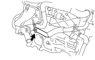
Disconnect the No. 3 water by-pass hose from the water inlet housing.
-
DISCONNECT WATER INLET HOSE
-
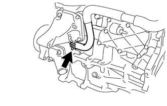
Disconnect the water inlet hose from the water inlet housing.
-
REMOVE WATER INLET
REMOVE THERMOSTAT
REMOVE IGNITION COIL ASSEMBLY
REMOVE CYLINDER HEAD COVER SUB-ASSEMBLY
REMOVE CYLINDER HEAD COVER GASKET
REMOVE SPARK PLUG TUBE GASKET
SET NO. 1 CYLINDER TO TDC/COMPRESSION
REMOVE CRANKSHAFT PULLEY
REMOVE NO. 1 CHAIN TENSIONER ASSEMBLY
REMOVE TIMING CHAIN COVER SUB-ASSEMBLY
-
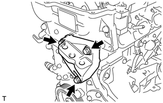
Remove the 3 bolts and engine mounting bracket.
-
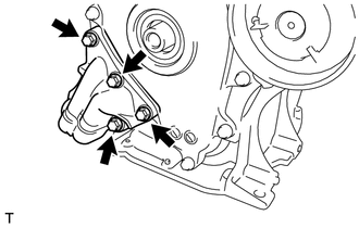
Remove the 4 bolts and oil filter bracket.
-
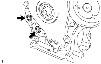
Remove the 2 O-rings.
-
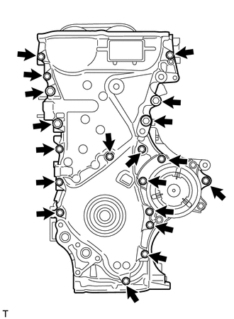
Remove the 19 bolts.
-
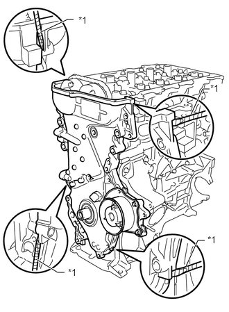
Remove the timing chain cover by prying between the timing chain cover and cylinder head, camshaft housing, cylinder block and stiffening crankcase with a screwdriver as shown in the illustration.
Table 1. Text in Illustration *1
Protective Tape
Tip:Tape the screwdriver tip before use.
Note:Be careful not to damage the contact surfaces of the cylinder head, camshaft housing, cylinder block, stiffening crankcase and timing chain cover.
-
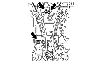
Remove the 3 O-rings.
-
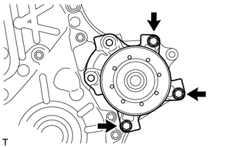
Remove the 3 bolts and water pump.
-
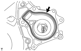
Remove the gasket.
-
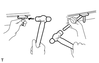
REMOVE TIMING CHAIN COVER OIL SEAL
-
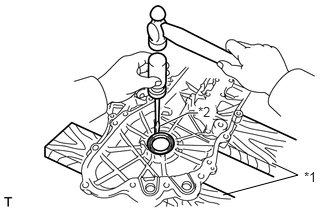
Place the timing chain cover on wooden blocks.
Table 2. Text in Illustration *1
Wooden Block
*2
Protective Tape
Using a screwdriver, tap out the oil seal.
Tip:Tape the screwdriver tip before use.
Note:Do not damage the surface of the oil seal press fit hole.
-
REMOVE CHAIN TENSIONER SLIPPER
REMOVE NO. 1 CHAIN VIBRATION DAMPER
REMOVE CHAIN SUB-ASSEMBLY
REMOVE CRANKSHAFT TIMING SPROCKET
-
Remove the crankshaft timing sprocket.
-
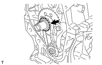
REMOVE NO. 2 CHAIN SUB-ASSEMBLY
-
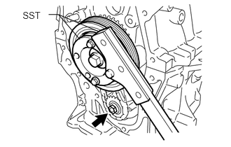
Temporarily install the crankshaft pulley and crankshaft pulley bolt.
Using SST, hold the crankshaft. Then remove the drive shaft gear nut.
for 86 mm (3.39 in.) Bolt Pitch Type:
09213-58014
91551-80840
09330-00021
for 64 mm (2.52 in.) Bolt Pitch Type:
09213-54015
09330-00021
Tip:For the 64 mm (2.52 in.) bolt pitch type, the part number of the installation bolt for SST (crankshaft pulley holding tool) is 91551-00850 (quantity: 2).
Remove SST, the crankshaft pulley bolt and crankshaft pulley.
-
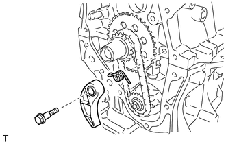
Remove the bolt, chain tensioner plate and spring.
-
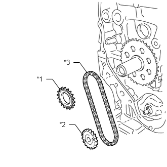
Remove the oil pump drive gear, oil pump drive shaft gear and No. 2 chain.
Table 3. Text in Illustration *1
Oil Pump Drive Gear
*2
Oil Pump Drive Shaft Gear
*3
No. 2 Chain Sub-assembly
-
REMOVE NO. 2 OIL PAN SUB-ASSEMBLY
-
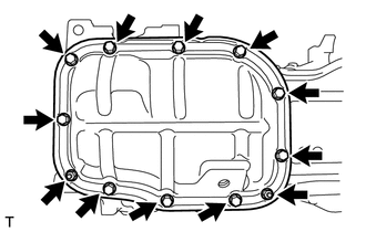
Remove the 10 bolts and 2 nuts.
-
Insert the blade of an oil pan seal cutter between the crankcase and oil pan. Cut through the sealer and remove the oil pan.
Note:Be careful not to damage the surface of the oil pan which contacts the stiffening crankcase.
Be careful not to damage the stiffening crankcase flange.
-
REMOVE OIL PUMP ASSEMBLY
-
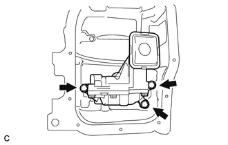
Remove the 3 bolts and oil pump.
-