EXHAUST FUEL ADDITION INJECTOR INSTALLATION
-
INSTALL EXHAUST FUEL ADDITION INJECTOR ASSEMBLY
-
Install a new No. 1 fuel injector back-up ring, No. 2 fuel injector back-up ring, O-ring and No. 3 fuel injector back-up ring to the exhaust fuel addition injector assembly.
-
Install a new E-ring to the exhaust fuel addition injector assembly.
-
Install a new gasket and the exhaust fuel addition injector assembly to the No. 1 injector holder.
-
-
INSTALL NO. 2 NOZZLE HOLDER CLAMP
-
Using a T40 "TORX" socket wrench, install the No. 2 nozzle holder clamp with the bolt.
- Torque:
- 12 N*m { 117 kgf*cm, 8 ft.*lbf }
-
-
INSTALL INJECTOR HOLDER
-
Install the injector holder to the No. 1 injector holder with the 2 bolts.
- Torque:
- 10 N*m { 102 kgf*cm, 7 ft.*lbf }
-
-
INSTALL NO. 2 EXHAUST MANIFOLD HEAT INSULATOR
-
Install a new gasket and the No. 2 exhaust manifold heat insulator to the No. 1 injector holder with the 3 nuts.
- Torque:
- 10 N*m { 102 kgf*cm, 7 ft.*lbf }
-
-
INSTALL NO. 1 INJECTOR HOLDER
-
Install the No. 1 injector holder to the exhaust manifold with 3 new nuts.
- Torque:
- 43 N*m { 438 kgf*cm, 32 ft.*lbf }
-
Connect the connector to the exhaust fuel addition injector assembly.
-
-
CONNECT NO. 5 WATER BY-PASS HOSE
-
Connect the No. 5 water by-pass hose to the No. 1 injector holder, and slide the clamp to secure the hose.
-
-
CONNECT NO. 4 WATER BY-PASS HOSE
-
Connect the No. 4 water by-pass hose to the No. 1 injector holder, and slide the clamp to secure the hose.
-
-
INSTALL NO. 1 FUEL PIPE
-
Connect the No. 1 fuel pipe to the No. 4 fuel pipe.
-
Install a new gasket and the No. 1 fuel pipe to the cylinder head cover sub-assembly and No. 1 injector holder with the union bolt and bolt.
- Torque:
- for bolt
- 10 N*m { 102 kgf*cm, 7 ft.*lbf }
- for union bolt
- 36 N*m { 367 kgf*cm, 27 ft.*lbf }
-
-
INSTALL ENGINE SERVICE HOLE SUB COVER SUB-ASSEMBLY
-
Install the engine service hole sub cover sub-assembly with the 5 bolts.
- Torque:
- 13 N*m { 133 kgf*cm, 10 ft.*lbf }
-
Return the floor carpet to its original position.
-
-
INSTALL FRONT DOOR SCUFF PLATE RH
-
INSTALL FRONT SEAT ASSEMBLY RH
-
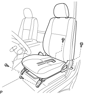
Connect the front seat inner belt assembly connector and install the front seat assembly.
-
Align the front seat assembly adjuster pin with the holes in the body.
-
Move the front seat assembly to the rearmost position.
Note
Make sure that the front seat assembly is securely locked.
-
Temporarily tighten the 2 bolts on the front side of the front seat assembly.
-
Move the front seat assembly fully forward.
Note
Make sure that the front seat assembly is securely locked.
-
Temporarily tighten the 2 bolts on the rear side of the front seat assembly.
-
Move the front seat assembly to the rearmost position.
Note
Make sure that the front seat assembly is securely locked.
-
Fully tighten the 2 bolts on the front side of the front seat assembly in the order of outer and inner side.
- Torque:
- 39 N*m { 398 kgf*cm, 29 ft.*lbf }
-
Move the front seat assembly fully forward.
Note
Make sure that the front seat assembly is securely locked.
-
Fully tighten the 2 bolts on the rear side of the front seat assembly in the order of outer and inner side.
- Torque:
- 39 N*m { 398 kgf*cm, 29 ft.*lbf }
-
-
INSTALL SEAT TRACK COVER LH
-
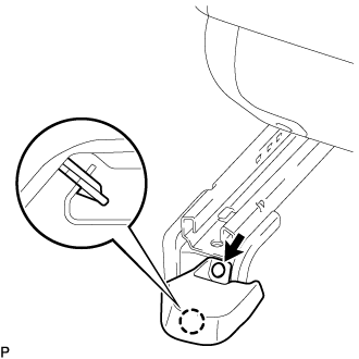
Attach the claw and install a new seat track cover LH with a new clip.
-
-
BLEED AIR FROM FUEL SYSTEM
-
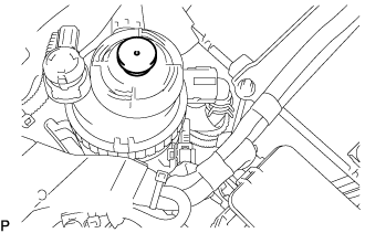
Using the hand pump mounted on the fuel filter cap, bleed air from the fuel system. Continue pumping until the pump resistance increases.
Note
-
The maximum hand pump pumping speed is 2 strokes per second.
-
The hand pump must be pushed with a full stroke during pumping.
-
When the fuel pressure at the supply pump inlet port reaches a saturated pressure, the hand pump resistance increases.
-
If pumping is interrupted during the air bleeding process, fuel in the fuel line may return to the fuel tank. Continue pumping until the hand pump resistance increases.
-
If the hand pump resistance does not increase despite consecutively pumping 200 times or more, there may be a fuel leak between the fuel tank and fuel filter, the hand pump may be malfunctioning, or the vehicle may have run out of fuel.
-
If air bleeding using the hand pump is incomplete, the common rail pressure does not rise to the pressure range necessary for normal use and the engine cannot be started.
-
-
Check if the engine starts.
Note
-
Even if air bleeding using the hand pump has been completed, the starter may need to be cranked for 10 seconds or more to start the engine.
-
Do not crank the engine continuously for more than 20 seconds. The battery may be discharged.
-
Use a fully-charged battery.
-
When the engine can be started, proceed to the next step.
-
If the engine cannot be started, bleed air again using the hand pump until the hand pump resistance increases (refer to the procedures above). Then start the engine.
-
-
Turn the ignition switch off.
-
Connect the GTS to the DLC3.
-
Turn the ignition switch to ON and turn the GTS on.
-
Clear the DTCs Click here.
-
Start the engine.*1
-
Enter the following menus: Powertrain / Engine and ECT / Active Test / Test the Fuel Leak.*2
-
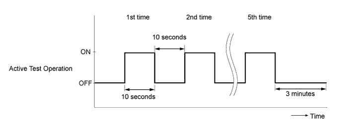
Perform the following test 5 times with on/off intervals of 10 seconds: Active Test / Test the Fuel Leak.*3
-
Allow the engine to idle for 3 minutes or more after performing the Active Test for the 5th time.
Tech Tips
When the Active Test "Test the Fuel Leak" is used to change the pump control mode, the actual fuel pressure inside the common rail drops below the target fuel pressure when the Active Test is off, but this is normal and does not indicate a pump malfunction.
-
Enter the following menus: Powertrain / Engine and ECT /Trouble Codes.
-
Read Current DTCs.
-
Clear the DTCs Click here.
Tech Tips
It is necessary to clear the DTCs as DTC P1604 or P1605 may be stored when air is bled from the fuel system after replacing or repairing fuel system parts.
-
Repeat steps *1 to *3.
-
Enter the following menus: Powertrain / Engine and ECT / Trouble Codes.
-
Read Current DTCs.
OK No DTCs are output.
-
-
ADD ENGINE COOLANT
-
Firmly tighten the drain plugs.
-
Fill the radiator reserve tank assembly with engine coolant to the top of the inlet.
Standard capacity 13.9 liters (14.6 US qts, 12.2 Imp qts) Note
Do not substitute plain water for engine coolant.
Tech Tips
-
Use of improper coolants may damage the engine cooling system.
-
Use only TOYOTA Super Long Life Coolant (SLLC) or similar high quality ethylene glycol based non-silicate, non-amine, non-nitrite, and non-borate coolant with long-life hybrid organic acid technology (coolant with long-life hybrid organic acid technology consists of a combination of low phosphates and organic acids).
-
-
Loosen the bleeder plug of the water outlet sub-assembly.
-
When air is bled and the engine coolant drains out, firmly tighten the bleeder plug.
- Torque:
- 8.0 N*m { 82 kgf*cm, 71 in.*lbf }
-
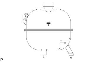
Add engine coolant up to the B line mark in the radiator reserve tank assembly and install the radiator cap sub-assembly.
-
Warm up the engine until the thermostat opens.
-
While the thermostat is open, circulate the engine coolant for several minutes.
Tech Tips
The thermostat open timing can be confirmed by pressing the No. 3 radiator hose by hand, and checking when the engine coolant starts to flow inside the hose.
-
-
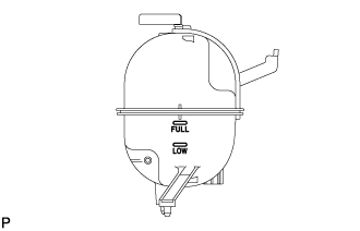
After the engine cools down, check that the engine coolant level is between the LOW and FULL line.
-
-
INSPECT FOR COOLANT LEAK
CAUTION:
Do not remove the radiator cap sub-assembly while the engine assembly and radiator assembly are still hot. Hot, pressurized engine coolant and steam may be released and cause serious burns.
-
Fill the radiator assembly with coolant and attach a radiator cap tester to the radiator.
-
Warm up the engine.
-
Using a radiator cap tester, increase the pressure inside the radiator assembly to 137 kPa (1.4 kgf/cm2, 19.9 psi), and check that the pressure does not drop.
Tech Tips
If the pressure drops, check the hoses, radiator assembly and engine water pump assembly for leaks. If no external leaks are found, check the heater core, cylinder block sub-assembly and cylinder head sub-assembly.
-