THEFT DETERRENT SYSTEM Intrusion Sensor Cancel Switch Circuit
| DTC Code | DTC Name |
|---|---|
| Intrusion Sensor Cancel Switch Circuit |
DESCRIPTION
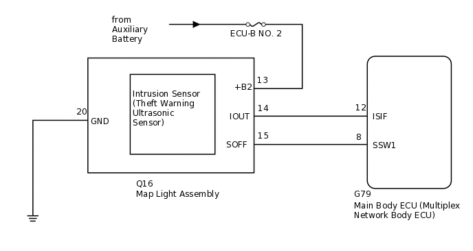
When the intrusion sensor cancel switch on the map light assembly is pressed, the sensor off signal is sent to the main body ECU (multiplex network body ECU) which causes the intrusion sensor to stop operating.
WIRING DIAGRAM
CAUTION / NOTICE / HINT
Inspect the fuses for circuits related to this system before performing the following inspection procedure.
When replacing the main body ECU (multiplex network body ECU), make sure to replace it with a new one.
PROCEDURE
READ VALUE USING GTS (INTRUSION SENS OFF SW)
Connect the GTS to the DLC3.
Turn the power switch on (IG).
Turn the GTS on.
Enter the following menus: Body Electrical / Main Body / Data List.
According to the display on the GTS, read the Data List.
Body Electrical > Main Body > Data List
Tester Display
Measurement Item
Range
Normal Condition
Diagnostic Note
Intrusion Sens OFF SW
Intrusion sensor cancel switch
ON or OFF
ON: Intrusion sensor cancel switch on
OFF: Intrusion sensor cancel switch off
-
Body Electrical > Main Body > Data List
Tester Display
Intrusion Sens OFF SW
OK
The indicator on the GTS switches between ON and OFF in accordance with the intrusion sensor cancel switch status.
Result
Proceed to
OK
NG
CHECK HARNESS AND CONNECTOR (MAIN BODY ECU [MULTIPLEX NETWORK BODY ECU] - MAP LIGHT ASSEMBLY AND BODY GROUND)
Disconnect the G79 main body ECU (multiplex network body ECU) connector.
Disconnect the Q16 map light assembly connector.
Measure the resistance according to the value(s) in the table below.
Standard Resistance
Tester Connection
Condition
Specified Condition
G79-8 (SSW1) - Q16-15 (SOFF)
Always
Below 1 Ω
Q16-20 (GND) - Body ground
Always
Below 1 Ω
G79-8 (SSW1) - Body ground
Always
10 kΩ or higher
Q16-15 (SOFF) - Body ground
Always
10 kΩ or higher
Result
Proceed to
OK
NG
NG REPAIR OR REPLACE HARNESS OR CONNECTOR
INSPECT MAP LIGHT ASSEMBLY (INTRUSION SENSOR CANCEL SWITCH)
-
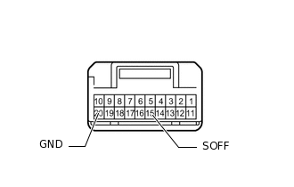
Remove the map light assembly (intrusion sensor cancel switch).
Measure the resistance according to the value(s) in the table below.
Standard Resistance
Tester Connection
Condition
Specified Condition
15 (SOFF) - 20 (GND)
Intrusion sensor cancel switch not pressed
10 kΩ or higher
15 (SOFF) - 20 (GND)
Intrusion sensor cancel switch pressed
Below 1 Ω
Result
Proceed to
OK
NG
-