STEERING COLUMN ASSEMBLY DISASSEMBLY
-
REMOVE STEERING SLIDING WITH COUPLING YOKE SUB-ASSEMBLY
-
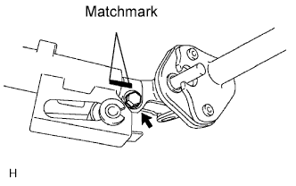
Make matchmarks on the steering main shaft and yoke.
-
Remove the bolt and yoke.
-
-
REMOVE NO.2 STEERING INTERMEDIATE SHAFT SUB-ASSEMBLY
-
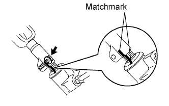
Make matchmarks on the intermediate shaft and steering link.
-
Remove the bolt and intermediate shaft from the steering link.
-
-
INSPECT STEERING COLUMN ASSEMBLY
-
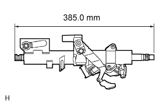
Measure the length of the steering main shaft.
Standard length 385.0 mm (15.157 in.)
-
-
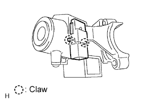
REMOVE TRANSPONDER KEY AMPLIFIER (w/ Engine Immobiliser System)
-
Using a screwdriver, widen the claw attached to the upper bracket by approximately 1.0 mm (0.039 in.).
-
Pull out the transponder key amplifier with the claw open.
-
Disconnect the amplifier connector and remove the transponder key amplifier.
-
-
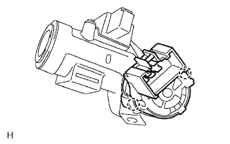
REMOVE KEY CYLINDER LIGHT ASSEMBLY (w/ Key Cylinder Light)
-
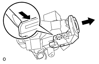
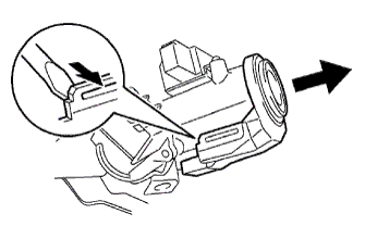
Using a screwdriver, detach the claw key cylinder light assembly in the direction indicated by the arrow in the illustration and remove it.
-
Disconnect the connector.
-
-
REMOVE STEERING COLUMN UPPER WITH SWITCH BRACKET ASSEMBLY
-
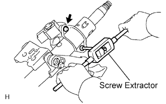
Using a 3 mm pin punch, mark the center of the 2 tapered-head bolts.
-
Using a 3 to 4 mm drill bit, drill into the 2 tapered-head bolts.
-
Using a screw extractor, remove the 2 bolts and bracket.
-
-
REMOVE STEERING COLUMN UPPER CLAMP
-
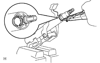
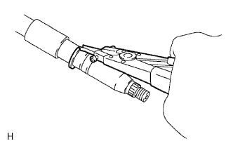
REMOVE IGNITION SWITCH LOCK CYLINDER ASSEMBLY
-
Turn the ignition switch to ACC.
-
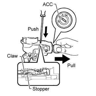
Insert the tip of a screwdriver into the hole in the steering column upper bracket, as shown in the illustration, and pull the ignition switch lock cylinder out until its claw comes into contact with the stopper of the steering column upper bracket.
Note
Pull the ignition switch lock cylinder assembly out until its claw comes into contact with the stopper of the steering column bracket assembly upper. Otherwise, the following procedure cannot be conducted properly.
-
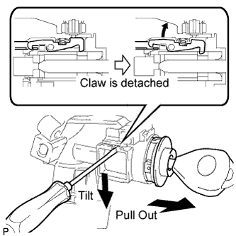
Insert the tip of a screwdriver into the hole in the steering column bracket and tilt it downward, as shown in the illustration, to detach the claw of the ignition switch lock cylinder. Then pull out the ignition switch lock cylinder.
-
-
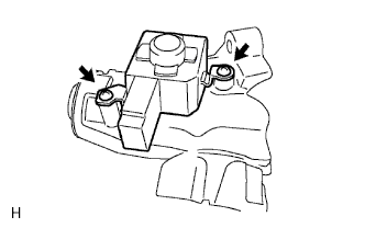
REMOVE UNLOCK WARNING SWITCH ASSEMBLY
-
Detach the 2 claws and remove the switch.
-
-
REMOVE IGNITION OR STARTER SWITCH ASSEMBLY
-
Detach the 2 claws and remove the switch from the steering column upper bracket.
-
-
REMOVE KEY INTER LOCK SOLENOID (for Automatic Transmission)
-
Remove the 2 screws and solenoid from the steering column upper bracket.
-
-
REMOVE STEERING MAIN SHAFT ASSEMBLY
-
Using a snap ring expander, remove the main shaft snap ring (outer side).
-
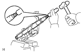
Using a brass bar and hammer, tap out the steering main shaft and steering main shaft bearing.
Note
Be careful not to drop the steering main shaft.
-
Using a snap ring expander, remove the steering main shaft snap ring (inner side).
-