AIR FUEL RATIO SENSOR INSTALLATION
PROCEDURE
INSTALL AIR FUEL RATIO SENSOR (for Bank 2 Sensor 1)
Temporarily install the air fuel ratio sensor to the exhaust manifold RH by hand.
-
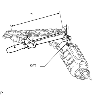
*1
Fulcrum Length
Using SST, tighten the air fuel ratio sensor.
09224-00010
without SST
44 N*m
449 kgf*cm
32 ft.*lbf
with SST
40 N*m
408 kgf*cm
30 ft.*lbf
Tip:Use a torque wrench with a fulcrum length of 30 cm (11.8 in.). When using a torque wrench with a fulcrum length that is not 30 cm (11.8 in.), calculate the torque specification for the torque wrench and SST based on the "without SST" torque specification (Click here).
Make sure SST and the wrench are connected in a straight line.
INSTALL AIR FUEL RATIO SENSOR (for Bank 1 Sensor 1)
Temporarily install the air fuel ratio sensor to the exhaust manifold LH by hand.
-
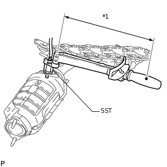
*1
Fulcrum Length
Using SST, tighten the air fuel ratio sensor.
09224-00010
without SST
44 N*m
449 kgf*cm
32 ft.*lbf
with SST
40 N*m
408 kgf*cm
30 ft.*lbf
Tip:Use a torque wrench with a fulcrum length of 30 cm (11.8 in.). When using a torque wrench with a fulcrum length that is not 30 cm (11.8 in.), calculate the torque specification for the torque wrench and SST based on the "without SST" torque specification (Click here).
Make sure SST and the wrench are connected in a straight line.
INSTALL EXHAUST MANIFOLD ASSEMBLY
Install the exhaust manifold (Click here).
INSPECT FOR EXHAUST GAS LEAK