SEAT HEATER SYSTEM, Diagnostic DTC:B14B5
| DTC Code | DTC Name |
|---|---|
| B14B5 | Lost Communication with Front Seat Temperature Adjustment Switch LIN |
DESCRIPTION
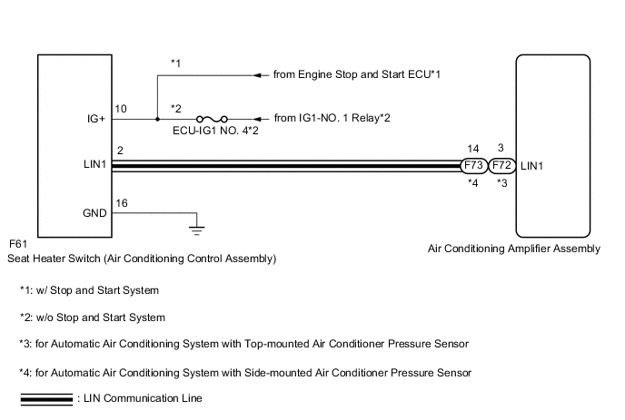
The seat heater switch (air conditioning control assembly) communicates with the air conditioning amplifier assembly via LIN communication.
If the LIN communication system is malfunctioning, the air conditioning amplifier assembly will not operate even if the seat heater switch (air conditioning control assembly) is operated.
| DTC No. | Detection Item | DTC Detection Condition | Trouble Area |
|---|---|---|---|
| B14B5 | Lost Communication with Front Seat Temperature Adjustment Switch LIN | Lost communication with the seat heater switch (air conditioning control assembly) |
|
WIRING DIAGRAM
CAUTION / NOTICE / HINT
Note
-
Inspect the fuses for circuits related to this system before performing the following procedure.
-
When DTC B14B2 and B14B5 are output simultaneously, first perform troubleshooting for the air conditioning system.
-
for Automatic Air Conditioning System with Top-mounted Air Conditioner Pressure Sensor
-
for Automatic Air Conditioning System with Side-mounted Air Conditioner Pressure Sensor
PROCEDURE
-
CLEAR DTC
-
Clear the DTCs.
Body Electrical > Air Conditioner > Clear DTCsResult Proceed to NEXT
NEXT 
-
-
CHECK FOR DTC
-
Check for DTCs.
Body Electrical > Air Conditioner > Trouble CodesOK DTC B14B5 is not output. Result Proceed to OK NG
OK 
USE SIMULATION METHOD TO CHECK Click here
NG
-
-
CHECK HARNESS AND CONNECTOR (IG POWER SUPPLY - SEAT HEATER SWITCH (AIR CONDITIONING CONTROL ASSEMBLY) - BODY GROUND)
-
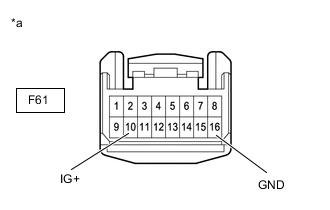
*a Front view of wire harness connector
(to Seat Heater Switch (Air Conditioning Control Assembly))
Disconnect the seat heater switch (air conditioning control assembly) connector.
-
Measure the voltage and resistance according to the value(s) in the table below.
Standard Voltage Tester Connection Switch Condition Specified Condition F61-10 (IG+) - Body ground Ignition switch ON 11 to 14 V*1
10.5 to 16 V*2
Ignition switch off Below 1 V
-
*1: w/o Stop and Start System
-
*2: w/ Stop and Start System
-
-
Measure the resistance according to the value(s) in the table below.
Standard Resistance Tester Connection Condition Specified Condition F61-16 (GND) - Body ground Always Below 1 Ω Result Result Proceed to OK A NG (w/o Stop and Start System) B NG (w/ Stop and Start System) C
B
REPAIR OR REPLACE HARNESS OR CONNECTOR
C
GO TO STOP AND START SYSTEM Click here
A
-
-
CHECK HARNESS AND CONNECTOR (AIR CONDITIONING AMPLIFIER ASSEMBLY - SEAT HEATER SWITCH (AIR CONDITIONING CONTROL ASSEMBLY))
-
Disconnect the F61 seat heater switch (air conditioning control assembly) connector.
-
Disconnect the F72*1 or F73*2 air conditioning amplifier assembly connector.
-
*1: for Automatic Air Conditioning System with Top-mounted Air Conditioner Pressure Sensor
-
*2: for Automatic Air Conditioning System with Side-mounted Air Conditioner Pressure Sensor
-
-
Measure the resistance according to the value(s) in the table below.
Standard Resistance for Automatic Air Conditioning System with Top-mounted Air Conditioner Pressure Sensor Tester Connection Condition Specified Condition F61-2 (LIN1) - F72-3 (LIN1) Always Below 1 Ω F61-2 (LIN1) or F72-3 (LIN1) - Body ground Always 10 kΩ or higher for Automatic Air Conditioning System with Side-mounted Air Conditioner Pressure Sensor Tester Connection Condition Specified Condition F61-2 (LIN1) - F73-14 (LIN1) Always Below 1 Ω F61-2 (LIN1) or F73-14 (LIN1) - Body ground Always 10 kΩ or higher Result Proceed to OK NG
NG
REPAIR OR REPLACE HARNESS OR CONNECTOR
OK
-
-
REPLACE SEAT HEATER SWITCH (AIR CONDITIONING CONTROL ASSEMBLY)
-
Temporarily replace the seat heater switch (air conditioning control assembly) with a new or known good one.
Result Proceed to NEXT
NEXT
-
-
CLEAR DTC
-
Clear the DTCs.
Body Electrical > Air Conditioner > Clear DTCsOK DTC B14B5 is not output. Result Proceed to NEXT
NEXT
-
-
CHECK FOR DTC
-
Check for DTCs.
Body Electrical > Air Conditioner > Trouble CodesOK DTC B14B5 is not output. Result Proceed to OK NG
OK
END (SEAT HEATER SWITCH (AIR CONDITIONING CONTROL ASSEMBLY) WAS DEFECTIVE)
NG
REPLACE AIR CONDITIONING AMPLIFIER ASSEMBLY Click here
-