MAIN BODY ECU REMOVAL
PROCEDURE
REMOVE UPPER INSTRUMENT PANEL
REMOVE LOWER INSTRUMENT PANEL FINISH PANEL
REMOVE DRIVER SIDE JUNCTION BLOCK ASSEMBLY WITH BODY ECU
-
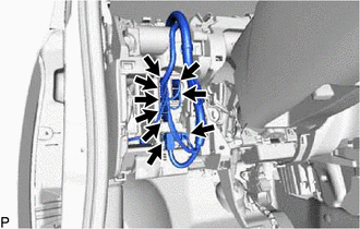
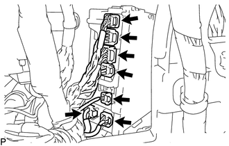
Disconnect each connector.
-
Disengage the clamp.
-
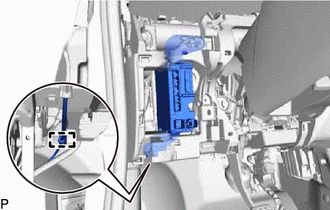
Remove the bolt and nut.
Pull out the driver side junction block assembly with body ECU.
-
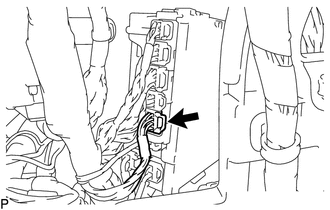
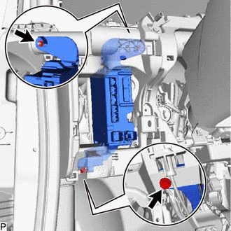
Disconnect the connector.
-
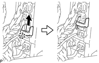
Disengage the claw and slide the connector lock as shown in the illustration.
-
Disconnect each connector and remove the driver side junction block assembly with body ECU.
-
REMOVE BODY ECU
-
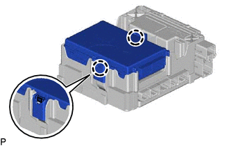
Press the 2 claws of the driver side junction block assembly to release the lock.
-
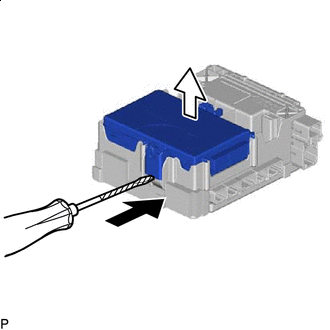

Protective Tape
With the driver side junction block assembly lock released, insert a screwdriver with its tip wrapped with protective tape horizontally between the body ECU and driver side junction block assembly.
Note:Use a screwdriver with a diameter between 5.0 mm (0.197 in.) and 6.3 mm (0.248 in.) and a length of approximately 90 mm (3.54 in.).
Do not insert the screwdriver under the connector socket of the body ECU.
Using the screwdriver, carefully raise the body ECU to the position where the connector becomes disconnected.
Note:Do not twist the screwdriver to raise the body ECU.
-