EXHAUST MANIFOLD INSTALLATION
PROCEDURE
-
INSTALL STUD BOLT
Tech Tips
If a stud bolt is deformed or its threads are damaged, replace it.
-
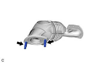
Using an E8 "TORX" socket wrench, install the 2 stud bolts to the exhaust manifold (TWC: Front Catalyst).
- Torque:
- 19.5 N*m { 199 kgf*cm, 14 ft.*lbf }
-
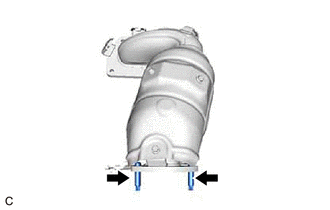
Using an E8 "TORX" socket wrench, install the 2 stud bolts to the exhaust manifold assembly LH (TWC: Front Catalyst).
- Torque:
- 19.5 N*m { 199 kgf*cm, 14 ft.*lbf }
-
-
INSTALL EXHAUST MANIFOLD TO HEAD GASKET (for Bank 2)
-
Install a new exhaust manifold to head gasket (for Bank 2) to the cylinder head sub-assembly.
-
-
INSTALL EXHAUST MANIFOLD ASSEMBLY LH (TWC: Front Catalyst)
-
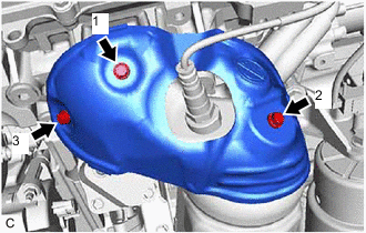
Temporarily install the exhaust manifold assembly LH (TWC: Front Catalyst) with the 4 nuts.
-
Temporarily install the No. 2 manifold stay to the exhaust manifold assembly LH (TWC: Front Catalyst) and cylinder block sub-assembly with the bolt and nut.
-
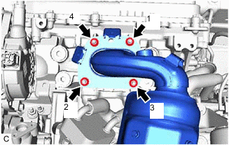
Using a 12 mm deep socket wrench, tighten the 4 nuts in the order shown in the illustration.
- Torque:
- 21 N*m { 214 kgf*cm, 15 ft.*lbf }
-
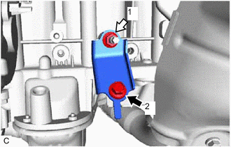

Bolt 
Nut Tighten the bolt and nut in the order shown in the illustration.
- Torque:
- 34 N*m { 347 kgf*cm, 25 ft.*lbf }
-
Connect the No. 1 radiator hose to the radiator assembly and slide the clip to secure it.
-
Connect the 2 No. 2 cooling fan motor connectors.
-
-
INSTALL AIR FUEL RATIO SENSOR (for Bank 2)
-
INSTALL NO. 2 EXHAUST MANIFOLD HEAT INSULATOR
-
Install the No. 2 exhaust manifold heat insulator to the exhaust manifold assembly LH (TWC: Front Catalyst) with the 3 bolts in the order shown in the illustration.
- Torque:
- 8.5 N*m { 87 kgf*cm, 75 in.*lbf }
-
Engage the wire harness clamp.
-
Connect the air fuel ratio sensor connector.
-
-
INSTALL V-BANK COVER SUB-ASSEMBLY
-
INSTALL ENGINE OIL LEVEL DIPSTICK GUIDE
-
INSTALL FRONT EXHAUST PIPE ASSEMBLY
-
INSTALL NO. 1 EXHAUST PIPE SUPPORT BRACKET (for Lower Side)
-
INSTALL EXHAUST MANIFOLD TO HEAD GASKET (for Bank 1)
-
Install a new exhaust manifold to head gasket (for Bank 1) to the cylinder head sub-assembly RH.
-
-
INSTALL EXHAUST MANIFOLD (TWC: Front Catalyst)
-
Temporarily install the exhaust manifold (TWC: Front Catalyst) with the 4 nuts.
-
Temporarily install the manifold stay to the exhaust manifold (TWC: Front Catalyst) and rear engine mounting bracket with the bolt and nut.
-
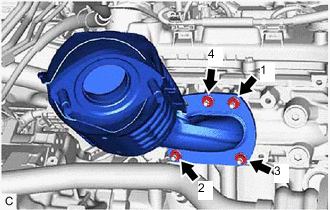
Using a 12 mm deep socket wrench, tighten the 4 nuts in the order shown in the illustration.
- Torque:
- 21 N*m { 214 kgf*cm, 15 ft.*lbf }
-
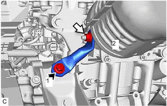
Bolt Nut Tighten the bolt and nut in the order shown in the illustration.
- Torque:
- 34 N*m { 347 kgf*cm, 25 ft.*lbf }
-
-
INSTALL FRONT NO. 3 EXHAUST PIPE SUB-ASSEMBLY
-
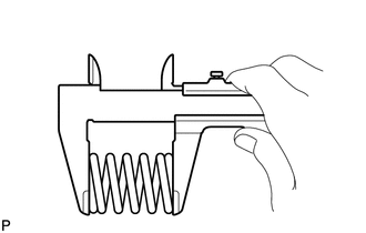
Using a vernier caliper, measure the free length of the 2 compression springs.
Standard Length 43.0 mm (1.69 in.) Minimum Free Length 41.5 mm (1.63 in.) If the free length is less than minimum, replace the compression spring.
-
Temporarily install a new exhaust pipe gasket to the front No. 3 exhaust pipe sub-assembly (center exhaust pipe assembly (TWC: Rear Catalyst) side).
-
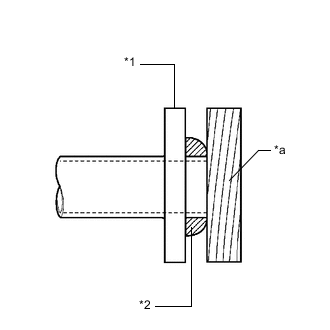
*1 Front No. 3 Exhaust Pipe Sub-assembly *2 Exhaust Pipe Gasket *a Wooden Block Using a plastic hammer and wooden block, tap in the exhaust pipe gasket until its surface is flush with the front No. 3 exhaust pipe sub-assembly.
Note
-
Be careful with the installation direction of the exhaust pipe gasket.
-
Do not reuse the exhaust pipe gasket.
-
Do not damage the exhaust pipe gasket.
-
Do not push in the exhaust pipe gasket by using the exhaust pipes when connecting them.
-
-
Install 2 new exhaust pipe gaskets to the front No. 3 exhaust pipe sub-assembly.
-
Temporarily install the front No. 3 exhaust pipe sub-assembly with the 4 bolts, 2 nuts and 2 compression springs.
-
Tighten the 2 bolts and 2 nuts.
- Torque:
- 55 N*m { 561 kgf*cm, 41 ft.*lbf }
-
Tighten the 2 bolts and 2 compression springs.
- Torque:
- 43 N*m { 438 kgf*cm, 32 ft.*lbf }
Tech Tips
After installation, check that the space between the flanges of the center exhaust pipe assembly (TWC: Rear Catalyst) and front No. 3 exhaust pipe sub-assembly is consistent front-to-rear and left-to-right.
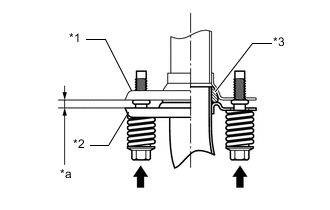
*1 Center Exhaust Pipe Assembly (TWC: Rear Catalyst) *2 Front No. 3 Exhaust Pipe Sub-assembly *3 Exhaust Pipe Gasket *a Space between Flanges: 8.5 mm (0.335 in.) -
Connect the heated oxygen sensor (for Bank 1) connector.
-
Engage the 4 wire harness clamps.
-
-
INSTALL FRONT FLOOR COVER LH
-
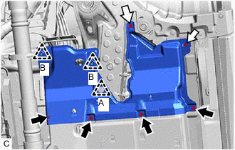
Bolt Screw Install the front floor cover LH with the 2 clips (B).
-
Install the clip (A), 2 screws and 4 bolts to the front floor cover LH.
-
-
INSTALL AIR FUEL RATIO SENSOR (for Bank 1)
-
INSTALL NO. 2 ENGINE UNDER COVER
-
ADD ENGINE COOLANT
-
INSPECT FOR COOLANT LEAK
-
INSPECT FOR EXHAUST GAS LEAK