RADIO RECEIVER INSTALLATION
CAUTION / NOTICE / HINT
Tech Tips
-
Use the same procedure for RHD and LHD vehicles.
-
The procedure listed below is for LHD vehicles.
PROCEDURE
-
INSTALL RADIO RECEIVER ASSEMBLY
-
INSTALL NO. 2 RADIO RECEIVER BRACKET
-
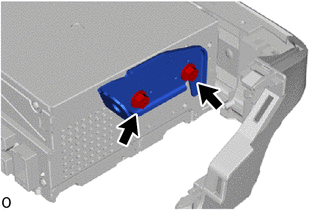
Install the No. 2 radio receiver bracket with the 2 screws.
- Torque:
- 2.0 N*m { 20 kgf*cm, 18 in.*lbf }
-
-
INSTALL NO. 1 RADIO RECEIVER BRACKET
-
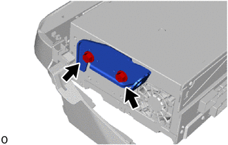
Install the No. 1 radio receiver bracket with the 2 screws.
- Torque:
- 2.0 N*m { 20 kgf*cm, 18 in.*lbf }
-
-
INSTALL NO. 1 NAVIGATION WIRE
-
INSTALL RADIO RECEIVER ASSEMBLY WITH BRACKET
-
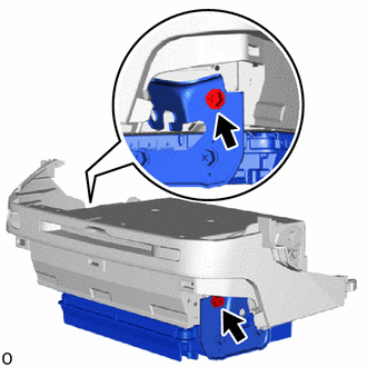
Install the radio receiver assembly with bracket and navigation ECU assembly with bracket with the 2 bolts.
- Torque:
- 2.0 N*m { 20 kgf*cm, 18 in.*lbf }
-
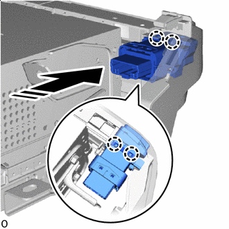

Install in this Direction Attach the claw to install the parking hold switch.
-
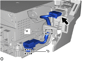
*a Guide *b Clamp Connect the connector.
-
Connect the clamp and the guide to install the switch wire.
-
Connect each connector.
-
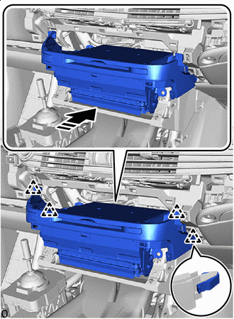
Install in this Direction Attach the clip to temporarily install the radio receiver assembly with bracket as shown in the illustration.
-
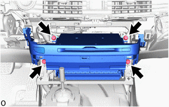
Install the radio receiver assembly with bracket with the 4 bolts.
-
-
INSTALL LOWER INSTRUMENT PANEL FINISH PANEL ASSEMBLY
-
INSTALL LOWER NO. 1 INSTRUMENT PANEL PAD SUB-ASSEMBLY
-
INSTALL INSTRUMENT SIDE PANEL RH
-
w/ Airbag Cut Off Switch:
-
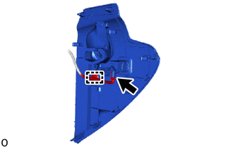
Connect the connector.
-
Attach the clamp.
-
-
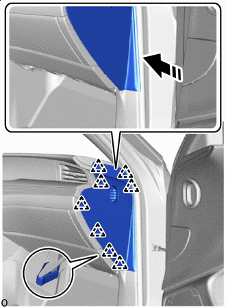
Install in this Direction Attach the clip and install the instrument side panel RH in the direction indicated by the arrow shown in the illustration.
-
-
INSTALL INSTRUMENT SIDE PANEL LH
-
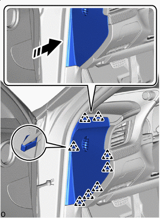
Install in this Direction Attach the clip and install the instrument side panel LH in the direction indicated by the arrow shown in the illustration.
-
-
INSTALL CONSOLE BOX ASSEMBLY
-
CONNECT CABLE TO NEGATIVE BATTERY TERMINAL
Note
When disconnecting the cable, some systems need to be initialized after the cable is reconnected.
-
INSTALL LUGGAGE COMPARTMENT MAT SUB-ASSEMBLY
-
PERFORM DIAGNOSTIC SYSTEM CHECK
-
INSPECT SRS WARNING LIGHT