FRONT DRIVE SHAFT ASSEMBLY(for 2WD) DISASSEMBLY
CAUTION / NOTICE / HINT
When using a vise, place aluminum plates between the part and vise.
When using a vise, do not overtighten it.
PROCEDURE
DISCONNECT FRONT NO. 2 AXLE INBOARD JOINT BOOT CLAMP LH
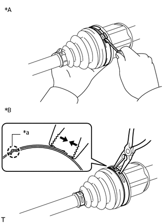
*A
for One Touch Type
*B
for Claw Engagement Type
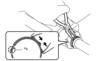
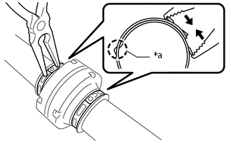
*a
Claw Engagement
for One Touch Type:
Using a screwdriver, disconnect the front No. 2 axle inboard joint boot clamp LH as shown in the illustration.
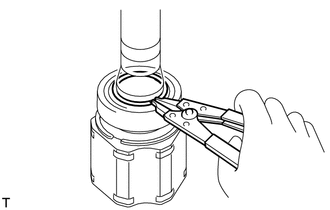
for Claw Engagement Type:
Using needle-nose pliers, detach the claw engagement and disconnect the front No. 2 axle inboard joint boot clamp LH.
DISCONNECT FRONT NO. 2 AXLE INBOARD JOINT BOOT CLAMP RH
Tip:Use the same procedure described for the LH side.
DISCONNECT FRONT AXLE INBOARD JOINT BOOT CLAMP LH
Tip:Use the same procedure described for the front No. 2 axle inboard joint boot clamp LH.
DISCONNECT FRONT AXLE INBOARD JOINT BOOT CLAMP RH
Tip:Use the same procedure described for the LH side.
DISCONNECT FRONT AXLE INBOARD JOINT BOOT
Tip:Use the same procedure for the RH and LH sides.
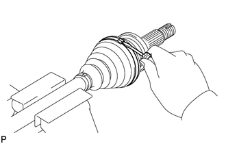
Disconnect the front axle inboard joint boot from the front drive inboard joint assembly.
REMOVE FRONT DRIVE INBOARD JOINT ASSEMBLY LH
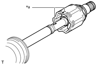
*a
Matchmark
Remove any old grease from the front drive inboard joint assembly LH.
Put matchmarks on the front drive inboard joint assembly LH and front drive outboard joint shaft assembly LH.
Note:Do not use a punch to make the matchmarks.
Remove the front drive inboard joint assembly LH from the front drive outboard joint shaft assembly LH.
-
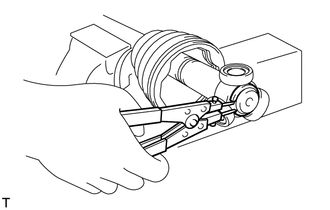
Using a snap ring expander, remove the snap ring.
-
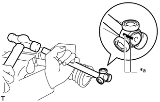
*a
Matchmark
Put matchmarks on the front drive outboard joint shaft assembly LH and tripod joint.
Note:Do not use a punch to make the matchmarks.
Using a brass bar and hammer, remove the tripod joint from the front drive outboard joint shaft assembly LH.
Note:Do not tap the rollers.
Do not drop the tripod joint.
Remove the front No. 2 axle inboard joint boot clamp LH, front axle inboard joint boot and front axle inboard joint boot clamp LH.
REMOVE FRONT DRIVE INBOARD JOINT ASSEMBLY RH
Tip:Use the same procedure described for the LH side.
DISCONNECT FRONT DRIVE SHAFT DAMPER CLAMP LH (w/ Drive Shaft Damper)
-
*a
Claw Engagement
w/ 1 Clamp:
Using needle-nose pliers, detach the claw engagement and disconnect the front drive shaft damper clamp LH.
-
*a
Claw Engagement
w/ 2 Clamps:
Using needle-nose pliers, detach the claw engagement and disconnect the 2 front drive shaft damper clamp LH.
Tip:Use the same procedure for each front drive shaft damper clamp LH.
-
DISCONNECT FRONT DRIVE SHAFT DAMPER CLAMP RH (w/ Drive Shaft Damper)
Tip:Use the same procedure described for the LH side.
REMOVE FRONT DRIVE SHAFT DAMPER LH (w/ Drive Shaft Damper)
w/ 1 Clamp:
Remove the front drive shaft damper LH and front drive shaft damper clamp LH from the front drive outboard joint shaft assembly LH.
w/ 2 Clamps:
Remove the front drive shaft damper LH and 2 front drive shaft damper clamp LH from the front drive outboard joint shaft assembly LH.
REMOVE FRONT DRIVE SHAFT DAMPER RH (w/ Drive Shaft Damper)
Tip:Use the same procedure described for the LH side.
DISCONNECT FRONT NO. 2 AXLE OUTBOARD JOINT BOOT CLAMP LH
Using a screwdriver, disconnect the front No. 2 axle outboard joint boot clamp LH as shown in the illustration.
DISCONNECT FRONT NO. 2 AXLE OUTBOARD JOINT BOOT CLAMP RH
Tip:Use the same procedure described for the LH side.
DISCONNECT FRONT AXLE OUTBOARD JOINT BOOT CLAMP LH
Tip:Use the same procedure described for the front No. 2 axle outboard joint boot clamp LH.
DISCONNECT FRONT AXLE OUTBOARD JOINT BOOT CLAMP RH
Tip:Use the same procedure described for the LH side.
REMOVE FRONT AXLE OUTBOARD JOINT BOOT
Tip:Use the same procedure for the RH and LH sides.
Remove the front No. 2 axle outboard joint boot clamp, front axle outboard joint boot and front axle outboard joint boot clamp from the front drive outboard joint shaft assembly.
Remove any old grease from the front drive outboard joint shaft assembly.
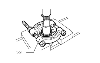
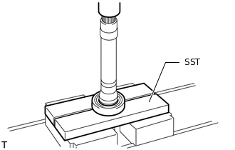
REMOVE FRONT DRIVE SHAFT DUST COVER LH
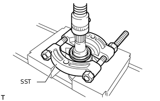
Using SST and a press, remove the front drive shaft dust cover LH from the front drive inboard joint assembly LH.
09950-00020
Note:Do not drop the front drive inboard joint assembly LH.
REMOVE FRONT DRIVE SHAFT DUST COVER RH
-
Using SST and a press, remove the front drive shaft dust cover RH from the front drive inboard joint assembly RH.
09950-00020
Note:Do not drop the front drive inboard joint assembly RH.
-
REMOVE DRIVE SHAFT BEARING CASE SUB-ASSEMBLY (for RH Side)
w/ Drive Shaft Bearing Case:
-
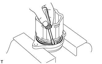
Using a screwdriver, remove the bearing case snap ring from the drive shaft bearing case sub-assembly.
-
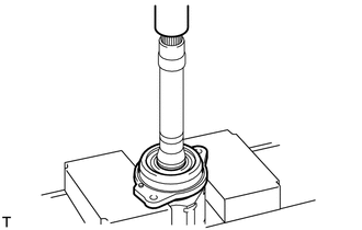
Using a press, remove the drive shaft bearing case sub-assembly from the front drive inboard joint assembly RH.
Note:Do not drop the front drive inboard joint assembly RH.
-
REMOVE FRONT DRIVE SHAFT DUST COVER (for RH Side)
-
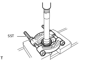
Using SST and a press, remove the front drive shaft dust cover from the front drive inboard joint assembly RH.
09950-00020
Note:Do not drop the front drive inboard joint assembly RH.
-
REMOVE FRONT DRIVE SHAFT BEARING (for RH Side)
Using a snap ring expander, remove the snap ring.
-
Using SST and a press, remove the front drive shaft bearing from the front drive inboard joint assembly RH.
09527-10011
Note:Do not drop the front drive inboard joint assembly RH.