VEHICLE STABILITY CONTROL SYSTEM TC and CG Terminal Circuit
| DTC Code | DTC Name |
|---|---|
| TC and CG Terminal Circuit |
DESCRIPTION
DTC output mode is set by connecting terminals TC and CG of the DLC3.
WIRING DIAGRAM
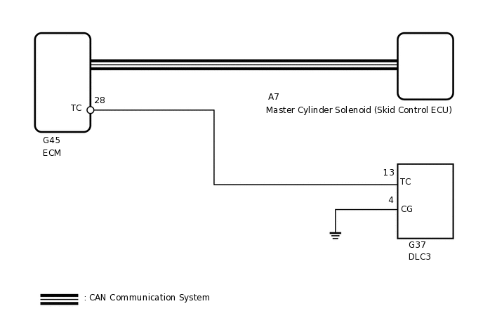
When each warning light continues blinking, a ground short in the wiring of terminal TC of the DLC3 or an internal ground short in each ECU is suspected.
CAUTION / NOTICE / HINT
When replacing the master cylinder solenoid, perform calibration (Click here).
PROCEDURE
INSPECT DLC3
Turn the engine switch on (IG).
-
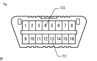
*a
Front view of DLC3
Measure the voltage according to the value(s) in the table below.
Standard Voltage
Tester Connection
Switch Condition
Specified Condition
G37-13 (TC) - G37-4 (CG)
Engine switch on (IG)
11 to 14 V
Result
Result
OK
NG
NG CHECK HARNESS AND CONNECTOR (ECM - DLC3)Click here
CHECK CAN COMMUNICATION LINE
Turn the engine switch off.
Connect the intelligent tester to the DLC3.
Turn the engine switch on (IG).
Turn the intelligent tester on.
Select CAN Bus Check from the System Selection Menu screen and follow the prompts on the screen to inspect the CAN bus.
OK
CAN Bus Check indicates no malfunctions in CAN communication.
Result
Result
OK
NG
CHECK DTC (CAN COMMUNICATION SYSTEM)
Turn the engine switch off.
Connect the intelligent tester to the DLC3.
Turn the engine switch on (IG).
Turn the intelligent tester on.
Check for DTCs.
Result
Result
Proceed to
CAN DTC is not output
A
CAN DTC is output
B
Body Electrical > PM1 Gateway > Trouble Codes
CHECK HARNESS AND CONNECTOR (ECM - DLC3)
Turn the engine switch off.
Disconnect the G45 ECM connector.
Measure the resistance according to the value(s) in the table below.
Standard Resistance
Tester Connection
Condition
Specified Condition
G45-28 (TC) - G37-13 (TC)
Always
Below 1 Ω
Result
Result
OK
NG
NG REPAIR OR REPLACE HARNESS OR CONNECTOR
CHECK HARNESS AND CONNECTOR (DLC3 - BODY GROUND)
Measure the resistance according to the value(s) in the table below.
Standard Resistance
Tester Connection
Condition
Specified Condition
G37-4 (CG) - Body ground
Always
Below 1 Ω
Result
Result
OK
NG
NG REPAIR OR REPLACE HARNESS OR CONNECTOR
CHECK ECM (DLC3 INPUT)
-
*a
Front view of DLC3
Using SST, connect terminals 13 (TC) and 4 (CG) of the DLC3.
Check that the MIL is blinking.
Result
Result
Proceed to
MIL is blinking
A
MIL is not blinking
B
09843-18040
B REPAIR OR REPLACE HARNESS OR CONNECTOR
-
CHECK DTC (CAN COMMUNICATION SYSTEM)
Turn the engine switch off.
Connect the intelligent tester to the DLC3.
Turn the engine switch on (IG).
Turn the intelligent tester on.
Check for DTCs.
Result
Result
Proceed to
CAN DTC is not output
A
CAN DTC is output
B
Body Electrical > PM1 Gateway > Trouble Codes