INTAKE MANIFOLD INSTALLATION
CAUTION / NOTICE / HINT
When replacing the injectors (including exchanging the injectors between the cylinders), common rail, intake manifold or cylinder head, it is necessary to replace the injection pipes with new ones.
When replacing the supply pump, common rail, intake manifold or cylinder head, it is necessary to replace the fuel inlet pipe with a new one.
PROCEDURE
INSTALL STUD BOLT
Tip:If a stud bolt is deformed or the threads are damaged, replace it.
-
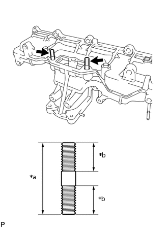
*a
40 mm (1.57 in.)
*b
16 mm (0.630 in.)
Install the 2 stud bolts to the intake manifold.
9.0 N*m
92 kgf*cm
80 in.*lbf
-
INSTALL INTAKE MANIFOLD
-
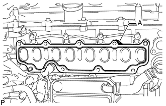
Install a new gasket to the cylinder head.
Tip:Install the gasket with the part (A) facing the right side of the vehicle as shown in the illustration.
-
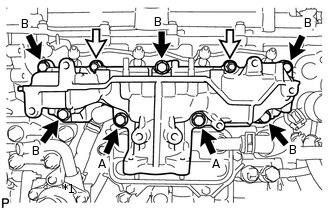

Bolt

Nut
Install the intake manifold with the 7 bolts and 2 nuts.
23 N*m
235 kgf*cm
17 ft.*lbf
Bolt Length
Item
Length
Bolt A
90 mm (3.54 in.)
Bolt B
25 mm (0.984 in.)
-
CONNECT NO. 2 VACUUM TRANSMITTING HOSE
Connect the No. 2 vacuum transmitting hose to the intake manifold and slide the clip to secure it.
CONNECT NO. 2 INTAKE MANIFOLD
Install a new gasket and No. 2 intake manifold with the bolt and 2 nuts.
24 N*m
245 kgf*cm
18 ft.*lbf
INSTALL ENGINE COVER BRACKET
Install the engine cover bracket with the bolt.
20 N*m
204 kgf*cm
15 ft.*lbf
INSTALL GAS FILTER BRACKET
Install the gas filter bracket with the 2 bolts.
8.8 N*m
90 kgf*cm
78 in.*lbf
INSTALL NO. 1 GAS FILTER
-
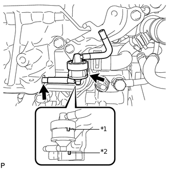
*1
Protrusion
*2
Groove
Install the No. 1 gas filter to the gas filter bracket.
Note:Make sure the protrusion of the No. 1 gas filter is aligned with the groove of the gas filter bracket.
Connect the vacuum hose.
-
INSTALL MANIFOLD ABSOLUTE PRESSURE SENSOR (DIESEL TURBO PRESSURE SENSOR)
INSTALL ENGINE OIL LEVEL DIPSTICK GUIDE
Install a new O-ring to the engine oil level dipstick guide.
Install the engine oil level dipstick guide with the 2 bolts.
24 N*m
245 kgf*cm
18 ft.*lbf
Connect the connector and then the wire harness clamp to the engine oil level dipstick guide.
Install the engine oil level dipstick.
INSTALL INTAKE MANIFOLD INSULATOR
Install the intake manifold insulator to the intake manifold.
INSTALL COMMON RAIL ASSEMBLY
INSTALL INJECTION PIPE SUB-ASSEMBLY
INSTALL FUEL INLET PIPE SUB-ASSEMBLY
INSTALL EGR VALVE (ELECTRIC EGR CONTROL VALVE ASSEMBLY)
INSTALL NO. 2 EGR PIPE SUB-ASSEMBLY
CONNECT NO. 8 WATER BY-PASS HOSE
CONNECT NO. 7 WATER BY-PASS HOSE
INSTALL EGR VALVE BRACKET
CONNECT ENGINE WIRE
INSTALL DIESEL THROTTLE BODY ASSEMBLY
BLEED AIR FROM FUEL SYSTEM
INSPECT FOR FUEL LEAK