WIRELESS DOOR LOCK CONTROL SYSTEM (for Non-built-in Type Door Control Receiver) Only Wireless Control Function is Inoperative
DESCRIPTION
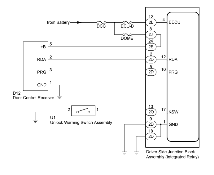
The door control receiver receives signals from the door control transmitter assembly and sends these signals to the driver side junction block assembly. The driver side junction block assembly then controls all doors by sending lock/unlock signals to each door.
WIRING DIAGRAM
INSPECTION PROCEDURE
Note
-
Inspect the fuses for circuits related to this system before performing the following inspection procedure.
-
When replacing the door control receiver or door control transmitter assembly, refer to the registration procedures Click here.
PROCEDURE
-
CHECK POWER DOOR LOCK OPERATION
-
Check the power door lock operation Click here.
OK Each door locks and unlocks normally.
NG 
Go to POWER DOOR LOCK CONTROL SYSTEM Click here
OK 
-
-
CHECK DOOR CONTROL TRANSMITTER ASSEMBLY
-
Check whether the wireless door lock control functions operate normally with another registered transmitter.
OK Wireless door lock control functions operate normally.
NG 
CHECK FOR ELECTRICAL NOISE Click here
OK
-
-
CHECK DOOR CONTROL TRANSMITTER ASSEMBLY (LED)
-
Press and hold the lock switch of the door control transmitter assembly for 5 seconds and check the number of times that the transmitter LED illuminates.
Result Result Proceed to Transmitter LED does not illuminate when switch is pressed and held A Transmitter LED illuminates 3 times or more when switch is pressed and held B Transmitter LED illuminates once or twice but not third time C
B
REPLACE DOOR CONTROL TRANSMITTER SUB-ASSEMBLY Click here
C
REPLACE TRANSMITTER BATTERY Click here
A
-
-
INSPECT TRANSMITTER BATTERY (VOLTAGE)
-
Remove the battery from the door control transmitter assembly that does not operate Click here.
-
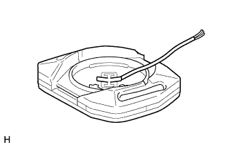
Attach a lead wire (0.6 mm (0.0236 in.) in diameter or less including wire sheath) with tape or equivalent to the negative terminal.
Note
Do not wrap the lead wire around a terminal, wedge it between the terminals or solder it. A terminal may be deformed or damaged, and the battery will not be able to be installed correctly.
-
Carefully extend the lead wire out from the position shown in the illustration and install the previously removed transmitter battery.
Note
When replacing the transmitter battery, before starting work, remove any static electricity that has built up by touching, for example, the vehicle to prevent the door control transmitter sub-assembly from being damaged.
-
Measure the voltage according to the value(s) in the table below.
Tech Tips
-
Measure the transmitter battery voltage while pressing the lock or unlock switch on the door control transmitter assembly.
-
Perform the measurement when the door control transmitter assembly is at room temperature.
Standard Voltage Tester Connection Condition Specified Condition Battery positive (+) - Battery negative (-) Ignition switch off, all doors closed and lock or unlock switch pushed 2.2 to 3.2 V -
NG
REPLACE TRANSMITTER BATTERY Click here
OK 
REPLACE DOOR CONTROL TRANSMITTER SUB-ASSEMBLY Click here
-
-
CHECK FOR ELECTRICAL NOISE
-
Move the door control transmitter assembly in the vicinity of the door control receiver.
Tech Tips
Refer to Parts Location for the location of the door control receiver Click here.
-
Press and hold either the lock or unlock transmitter switch for 1 second and check that the doors lock or unlock accordingly.
OK Wireless door lock control functions operate normally. Tech Tips
-
Check if electrical noise is the cause by moving the door control transmitter assembly closer to the door control receiver. Moving it closer will decrease the effects of electrical noise.
-
If the operation check can be performed normally, there is a high probability that electrical noise or a decrease in output from the door control transmitter assembly is the cause of the malfunction. There is a high probability that electrical noise is the cause if the problem occurs only in a certain location or only during a certain time of day. Also, custom components may be causing electrical noise. If custom components are installed in the vehicle, remove them and perform the operation check again.
-
NG
CHECK HARNESS AND CONNECTOR (DOOR CONTROL RECEIVER - DRIVER SIDE JUNCTION BLOCK) Click here
OK
FIND CAUSE OF NOISE AND REMOVE IT
-
-
CHECK HARNESS AND CONNECTOR (DOOR CONTROL RECEIVER - DRIVER SIDE JUNCTION BLOCK)
-
Disconnect the D12 door lock control receiver connector.
-
Disconnect the 2D and 2S driver side junction block assembly connectors.
-
Measure the resistance according to the value(s) in the table below.
Standard Resistance Tester Connection Condition Specified Condition D12-2 (RDA) - 2D-2 (RDA) Always Below 1 Ω D12-3 (PRG) - 2D-5 (PRG) Always Below 1 Ω D12-5 (+B) - 2S-24 Always Below 1 Ω D12-2 (RDA) or 2D-2 (RDA) - Body ground Always 10 kΩ or higher D12-3 (PRG) or 2D-5 (PRG) - Body ground Always 10 kΩ or higher D12-5 (+B) or 2S-24 - Body ground Always 10 kΩ or higher
NG
REPAIR OR REPLACE HARNESS OR CONNECTOR
OK
-
-
CHECK HARNESS AND CONNECTOR (DOOR CONTROL RECEIVER - BATTERY AND BODY GROUND)
-
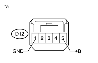
Text in Illustration *a Front view of wire harness connector
(to Door Control Receiver)
Disconnect the D12 door control receiver connector.
-
Measure the resistance according to the value(s) in the table below.
Standard Resistance Tester Connection Condition Specified Condition D12-1 (GND) - Body ground Always Below 1 Ω -
Measure the voltage according to the value(s) in the table below.
Standard Voltage Tester Connection Condition Specified Condition D12-5 (+B) - Body ground Always 11 to 14 V
NG
REPAIR OR REPLACE HARNESS OR CONNECTOR
OK
-
-
CHECK DOOR CONTROL RECEIVER (OUTPUT)
-
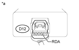
Text in Illustration *a Component with harness connected
(Door Control Receiver)
Measure the voltage according to the value(s) in the table below.
Standard Voltage Tester Connection Condition Specified Condition D12-2 (RDA) - Body ground Ignition switch off, all doors closed and transmitter switch not pressed 11 to 14 V Ignition switch off, all doors closed and transmitter switch pressed Pulse generation
NG
REPLACE DOOR CONTROL RECEIVER Click here
OK
-
-
INSPECT UNLOCK WARNING SWITCH ASSEMBLY
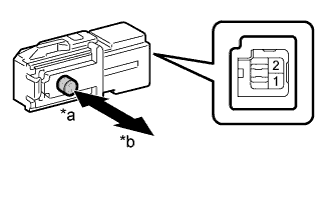
Text in Illustration *a Pushed *b Not pushed
-
Remove the unlock warning switch assembly.
-
Measure the resistance according to the value(s) in the table below.
Standard Resistance Tester Connection Switch Condition Specified Condition 1 - 2 Pushed Below 1 Ω Not pushed 10 kΩ or higher
NG
REPLACE UNLOCK WARNING SWITCH ASSEMBLY
OK
-
-
CHECK HARNESS AND CONNECTOR (UNLOCK WARNING SWITCH - DRIVER SIDE JUNCTION BLOCK AND BODY GROUND)
-
Disconnect the U1 unlock warning switch assembly connector.
-
Disconnect the 2O driver side junction block assembly connector.
-
Measure the resistance according to the value(s) in the table below.
Standard Resistance Tester Connection Condition Specified Condition 2O-10 (KSW) - U1-1 Always Below 1 Ω 2O-10 (KSW) or U1-1 - Body ground Always 10 kΩ or higher U1-2 - Body ground Always Below 1 Ω
NG
REPAIR OR REPLACE HARNESS OR CONNECTOR
OK
REPLACE DRIVER SIDE JUNCTION BLOCK ASSEMBLY
-