AUTOMATIC LIGHT CONTROL SENSOR INSPECTION
PROCEDURE
INSPECT AUTOMATIC LIGHT CONTROL SENSOR
-
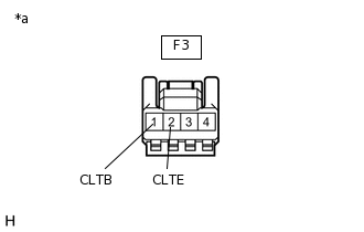
*a
Front view of wire harness connector
(to Automatic Light Control Sensor)
Disconnect the F3 automatic light control sensor connector.
Measure the voltage and resistance according to the value(s) in the table below.
Standard Voltage
Tester Connection
Condition
Specified Condition
F3-1 (CLTB) - F3-2 (CLTE)
Ignition switch off, dimmer switch off, 2 minutes after all doors closed
Below 1 V
Ignition switch ON
11 to 14 V
Standard Resistance
Tester Connection
Condition
Specified Condition
F3-2 (CLTE) - Body ground
Always
Below 1 Ω
If the result is not as specified, there may be a malfunction on the wire harness side.
-
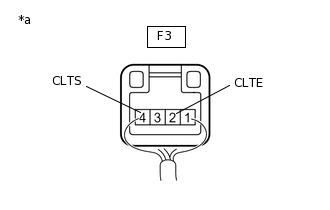
*a
Component with harness connected
(Automatic Light Control Sensor)
Reconnect the F3 automatic light control sensor connector.
Connect an oscilloscope to the automatic light control sensor connector.
-
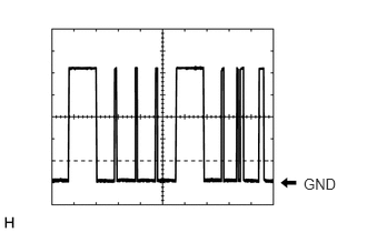
Check the waveform.
OK
Tester Connection
Tool Setting
Condition
Specified Condition
F3-4 (CLTS) - F3-2 (CLTE)
2 V/DIV., 10 ms./DIV.
Ignition switch ON
Correct waveform is as shown
Tip:The communication waveform changes according to the surrounding brightness.
If the result is not as specified, the automatic light control sensor may be malfunctioning.
-