FRAME(for 4WD and Pre-Runner) TWO-DIMENSIONAL DISTANCE
-
for Double Cab
-
Upper Face
Tech Tips
-
Length measurements are indicated at the points where the arrows extending from the zero point intersect the lines that extend towards the outside of the illustration from each point.
-
In cases in which only one dimension is given, left and right are symmetrical.
-
For symbols, capital letters indicate right side of vehicle, small letters indicate left side of vehicle (seen from rear).
Measuring Point Name Symbol Name Hole Diameter
mm (in.)
A, a Body Mounting Hole φ26 (1.02) B, b Shock Absorber Installation Hole φ12.2 (0.48) C, c Body Mounting Hole φ31 (1.22) D, d Side Rail Inner Channel Standard Hole 16X16
(0.63X0.63)
E, e Body Mounting Hole φ75 (2.95) F, f Rear Body Mounting Nut M12 (0.47) G, g Rear Body Mounting Hole φ24 (0.94) H, h Rear Body Mounting Hole φ24 (0.94) Wheel Base Wheel Base 3085 mm (121.46 in.) 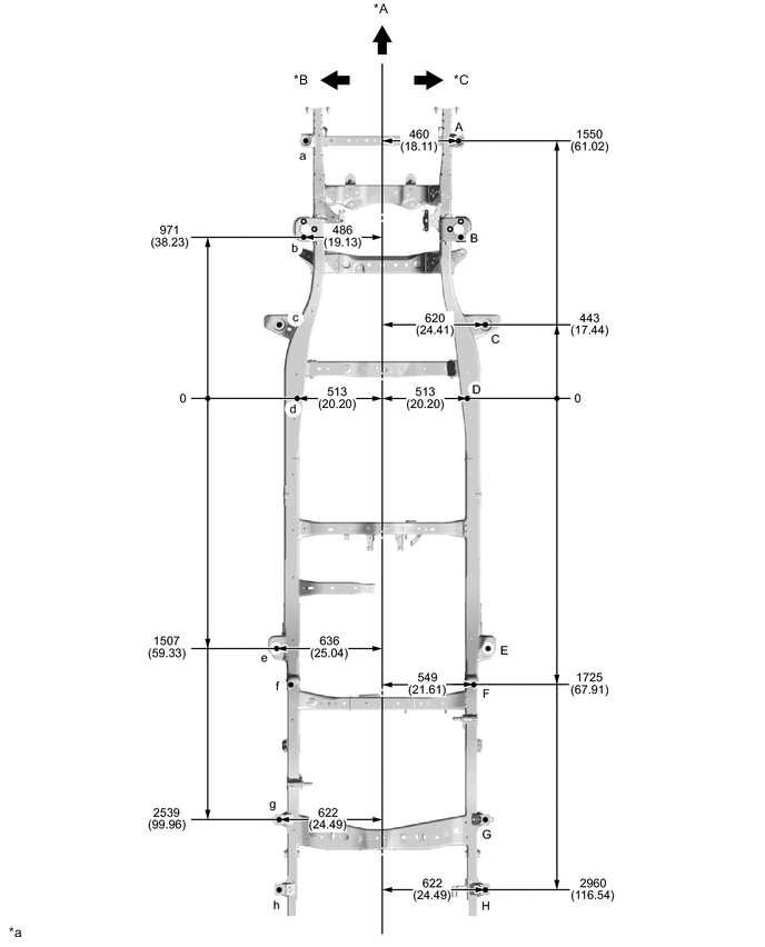
*A FRONT *B LH *C RH - - *a mm
(in.)
- - 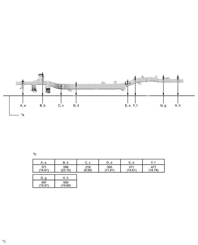
*a Imaginary Datum Line *b Height from Imaginary Datum Line *c mm
(in.)
- - -
-
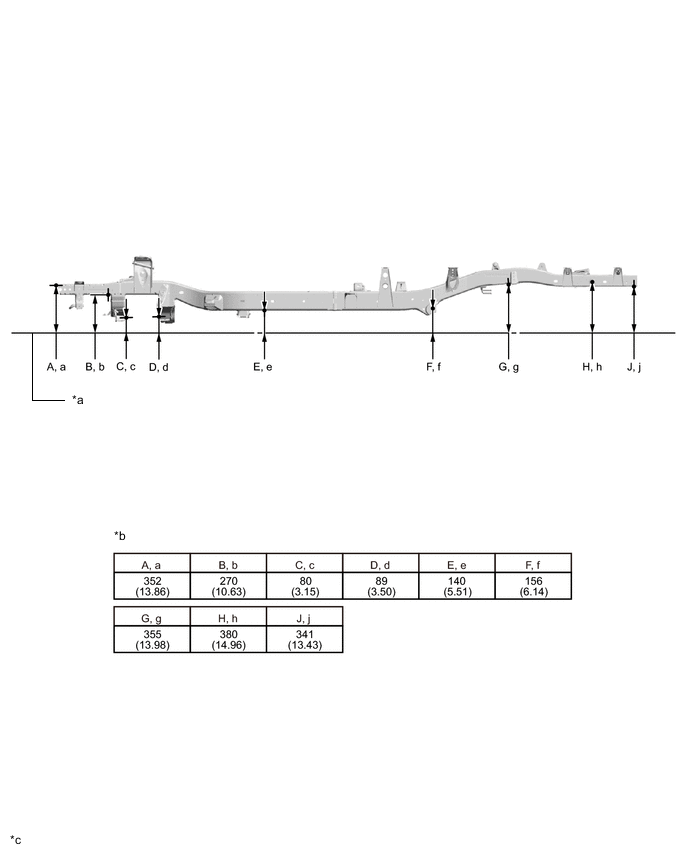
Lower Face
Tech Tips
-
Length measurements are indicated at the points where the arrows extending from the zero point intersect the lines that extend towards the outside of the illustration from each point.
-
In cases in which only one dimension is given, left and right are symmetrical.
-
For symbols, capital letters indicate right side of vehicle, small letters indicate left side of vehicle (seen from rear).
Measuring Point Name Symbol Name Hole Diameter
mm (in.)
A, a Bumper Reinforcement Installation Nut M10 (0.39) B, b Stabilizer Bracket Installation Nut M10 (0.39) C, c Suspension Lower Arm Installation Hole 16.5X34.5
(0.65X1.36)
D, d Suspension Lower Arm Installation Hole 16.5X34.5
(0.65X1.36)
E, e Side Rail Inner Channel Standard Hole 16X16
(0.63X0.63)
F, f Rear Spring Front Hanger Hole φ14.6 (0.57) G, g Rear Bumper Mounting Bracket Standard Hole φ9 (0.35) H, h Rear Spring Rear Hanger Hole φ30.35 (1.19) J, j Side Rail Outer Channel Standard Hole φ13 (0.51) Wheel Base Wheel Base 3085 mm (121.46 in.) 
*A FRONT *B LH *C RH - - *a mm
(in.)
- - 
*a Imaginary Datum Line *b Height from Imaginary Datum Line *c mm
(in.)
- - -
-
-
for Single Cab
-
Upper Face
Tech Tips
-
Length measurements are indicated at the points where the arrows extending from the zero point intersect the lines that extend towards the outside of the illustration from each point.
-
In cases in which only one dimension is given, left and right are symmetrical.
-
For symbols, capital letters indicate right side of vehicle, small letters indicate left side of vehicle (seen from rear).
Measuring Point Name Symbol Name Hole Diameter
mm (in.)
A, a Body Mounting Hole φ26 (1.02) B, b Shock Absorber Installation Hole φ12.2 (0.48) C, c Body Mounting Hole φ31 (1.22) D, d Side Rail Inner Channel Standard Hole 16X16
(0.63X0.63)
E, e Body Mounting Hole φ27 (1.06) F, f Rear Body Mounting Hole φ23 (0.91) G Rear Body Mounting Hole 23X15
(0.91X0.59)
g Rear Body Mounting Hole φ15 (0.59) H, h Rear Body Mounting Hole φ24 (0.94) J, j Rear Body Mounting Hole φ24 (0.94) Wheel Base Wheel Base 3085 mm (121.46 in.) 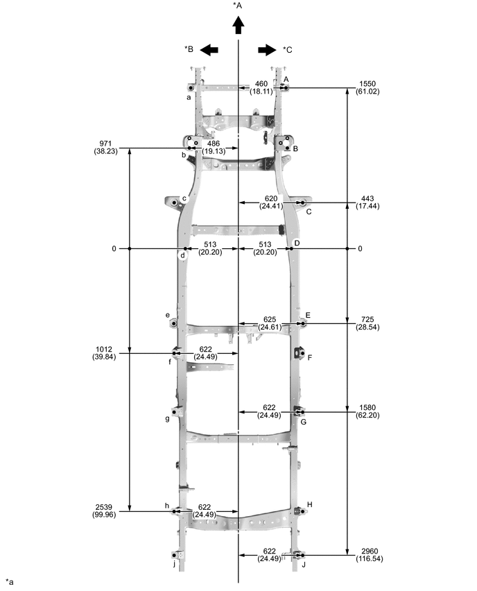
*A FRONT *B LH *C RH - - *a mm
(in.)
- - 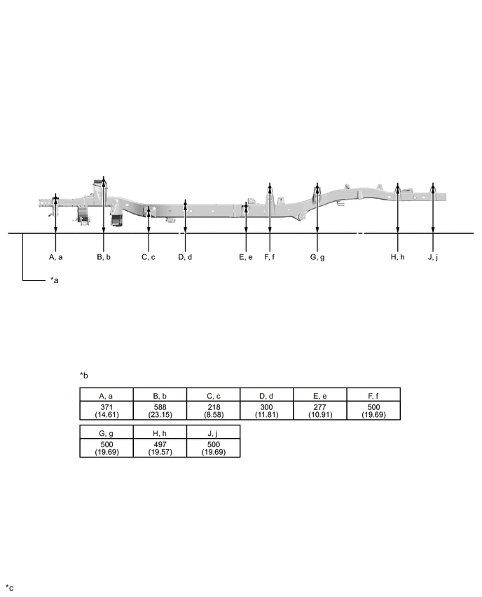
*a Imaginary Datum Line *b Height from Imaginary Datum Line *c mm
(in.)
- - -
-
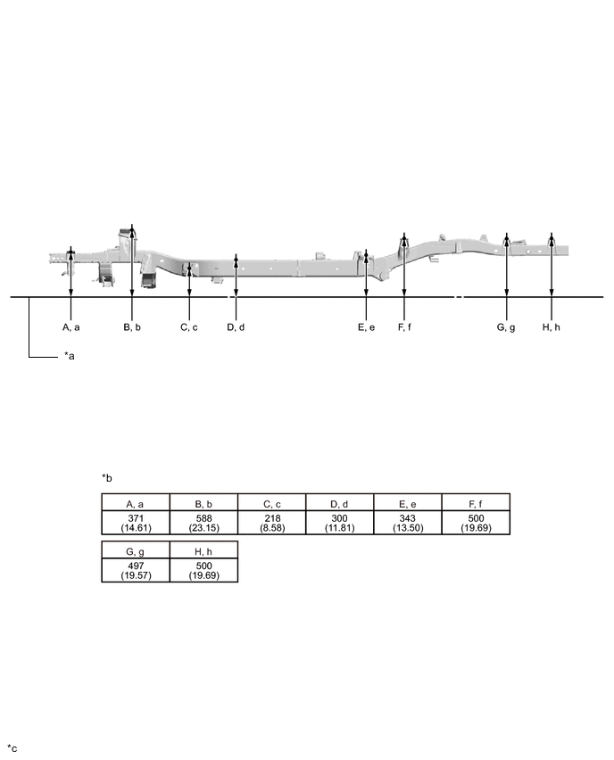
Lower Face
Tech Tips
-
Length measurements are indicated at the points where the arrows extending from the zero point intersect the lines that extend towards the outside of the illustration from each point.
-
In cases in which only one dimension is given, left and right are symmetrical.
-
For symbols, capital letters indicate right side of vehicle, small letters indicate left side of vehicle (seen from rear).
Measuring Point Name Symbol Name Hole Diameter
mm (in.)
A, a Bumper Reinforcement Installation Nut M10 (0.39) B, b Stabilizer Bracket Installation Nut M10 (0.39) C, c Suspension Lower Arm Installation Hole 16.5X34.5
(0.65X1.36)
D, d Suspension Lower Arm Installation Hole 16.5X34.5
(0.65X1.36)
E, e Side Rail Inner Channel Standard Hole 16X16
(0.63X0.63)
F, f Rear Spring Front Hanger Hole φ14.6 (0.57) G, g Rear Bumper Mounting Bracket Standard Hole φ9 (0.35) H, h Rear Spring Rear Hanger Hole φ30.35 (1.19) J, j Side Rail Outer Channel Standard Hole φ13 (0.51) Wheel Base Wheel Base 3085 mm (121.46 in.) 
*A FRONT *B LH *C RH - - *a mm
(in.)
- - 
*a Imaginary Datum Line *b Height from Imaginary Datum Line *c mm
(in.)
- - -
-
-
for Smart Cab
-
Upper Face
Tech Tips
-
Length measurements are indicated at the points where the arrows extending from the zero point intersect the lines that extend towards the outside of the illustration from each point.
-
In cases in which only one dimension is given, left and right are symmetrical.
-
For symbols, capital letters indicate right side of vehicle, small letters indicate left side of vehicle (seen from rear).
Measuring Point Name Symbol Name Hole Diameter
mm (in.)
A, a Body Mounting Hole φ26 (1.02) B, b Shock Absorber Installation Hole φ12.2 (0.48) C, c Body Mounting Hole φ31 (1.22) D, d Side Rail Inner Channel Standard Hole 16X16
(0.63X0.63)
E, e Body Mounting Hole φ75 (2.95) F Rear Body Mounting Hole 23X15
(0.91X0.59)
f Rear Body Mounting Hole φ15 (0.59) G, g Rear Body Mounting Hole φ24 (0.94) H, h Rear Body Mounting Hole φ24 (0.94) Wheel Base Wheel Base 3085 mm (121.46 in.) 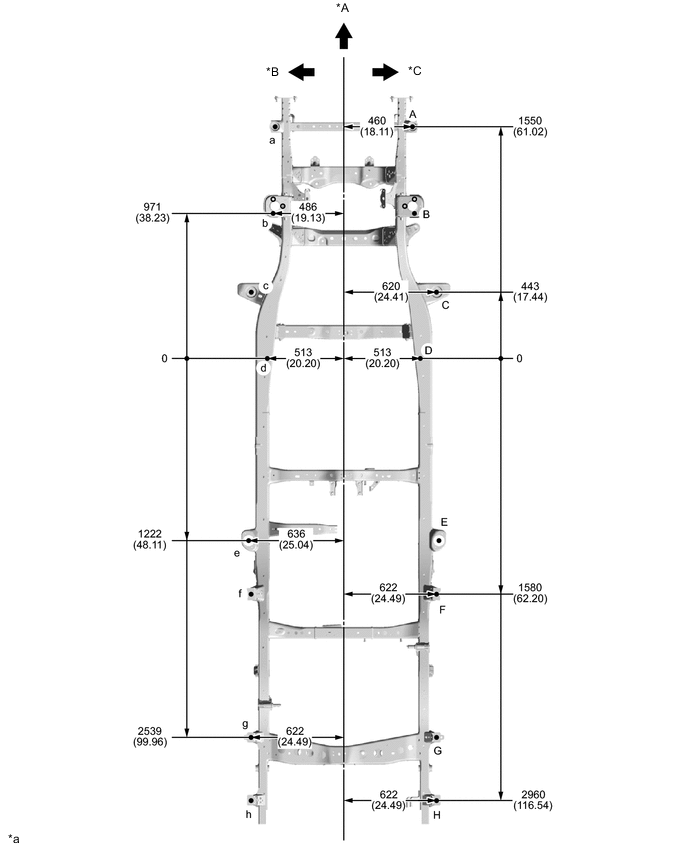
*A FRONT *B LH *C RH - - *a mm
(in.)
- - 
*a Imaginary Datum Line *b Height from Imaginary Datum Line *c mm
(in.)
- - -
-
Lower Face
Tech Tips
-
Length measurements are indicated at the points where the arrows extending from the zero point intersect the lines that extend towards the outside of the illustration from each point.
-
In cases in which only one dimension is given, left and right are symmetrical.
-
For symbols, capital letters indicate right side of vehicle, small letters indicate left side of vehicle (seen from rear).
Measuring Point Name Symbol Name Hole Diameter
mm (in.)
A, a Bumper Reinforcement Installation Nut M10 (0.39) B, b Stabilizer Bracket Installation Nut M10 (0.39) C, c Suspension Lower Arm Installation Hole 16.5X34.5
(0.65X1.36)
D, d Suspension Lower Arm Installation Hole 16.5X34.5
(0.65X1.36)
E, e Side Rail Inner Channel Standard Hole 16X16
(0.63X0.63)
F, f Rear Spring Front Hanger Hole φ14.6 (0.57) G, g Rear Bumper Mounting Bracket Standard Hole φ9 (0.35) H, h Rear Spring Rear Hanger Hole φ30.35 (1.19) J, j Side Rail Outer Channel Standard Hole φ13 (0.51) Wheel Base Wheel Base 3085 mm (121.46 in.) 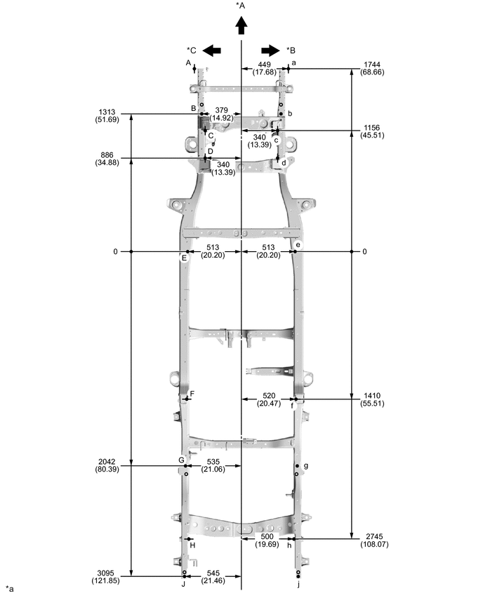
*A FRONT *B LH *C RH - - *a mm
(in.)
- - 
*a Imaginary Datum Line *b Height from Imaginary Datum Line *c mm
(in.)
- - -
-