TRANSMISSION CONTROL CABLE INSTALLATION
PROCEDURE
-
INSTALL TRANSMISSION CONTROL CABLE ASSEMBLY
Note
Before installing the transmission control cable assembly, check that the park/neutral position switch and shift lever are in neutral.
-
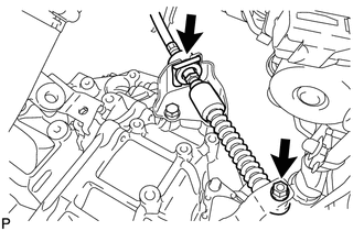
Put the transmission control cable into the cabin and connect the transmission control cable with the 2 nuts.
- Torque:
- 5.0 N*m { 51 kgf*cm, 44 in.*lbf }
-
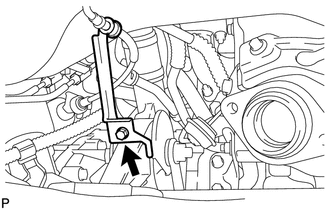
Connect the transmission control cable support with the bolt.
- Torque:
- 5.0 N*m { 51 kgf*cm, 44 in.*lbf }
-
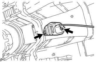
Connect the transmission control cable to the bracket with a new clip.
-
Connect the transmission control cable to the control shaft lever with the nut.
- Torque:
- 12 N*m { 122 kgf*cm, 9 ft.*lbf }
-
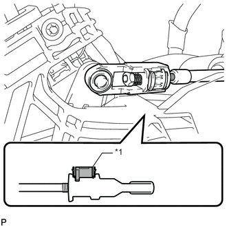
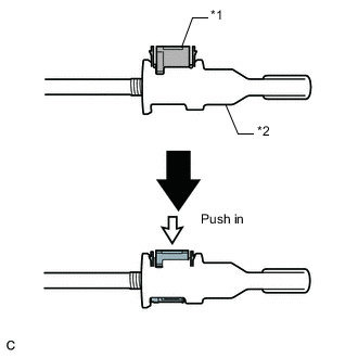
Turn the nut of the transmission control cable 180° counterclockwise. While holding the nut in place, push in the stopper until the stopper clicks twice.
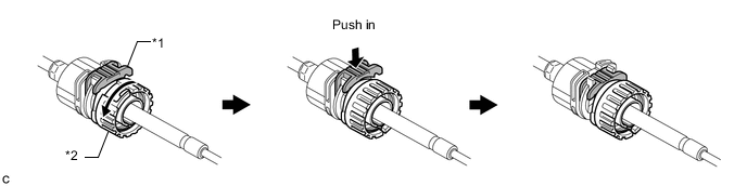
Text in Illustration *1 Stopper *2 Nut -
Install the outer part of the transmission control cable to the shift lever retainer. Check that the spring is positioned at "A" and push in the stopper.
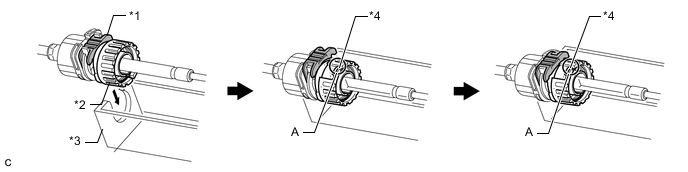
Text in Illustration *1 Stopper *2 Nut *3 Shift Lever Retainer *4 Spring Tech Tips
If the stopper cannot be pushed in, slightly turn the nut clockwise and then push in the stopper again.
-
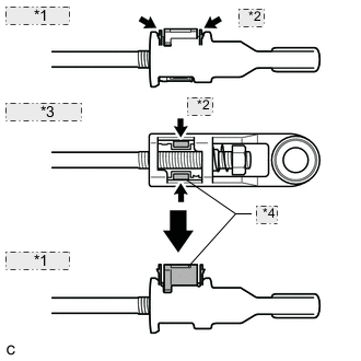
*1 Side View: *2 Push *3 Bottom View: *4 Lock Piece Push the 2 claws together at the top of the transmission control cable lock piece. While holding the 2 claws together, push the 2 lugs on the bottom of the lock piece toward each other and upward to pull out the lock piece.
-
Text in Illustration *1 Lock Piece Connect the end of the cable to the shift lever assembly.
Note
-
Make sure that the lock piece is pulled up.
-
Push on the end of the cable all the way to the base of the pin.
-
-
Text in Illustration *1 Lock Piece *2 Adjuster Case Push the lock piece into the adjuster case.
Note
Securely push in the lock piece until it locks.
-
-
INSTALL FRONT FLOOR NO. 1 HEAT INSULATOR
-
Install the heat insulator with the 5 nuts.
- Torque:
- 5.5 N*m { 56 kgf*cm, 49 in.*lbf }
-
-
INSTALL FRONT EXHAUST PIPE ASSEMBLY
-
CONNECT AIR FUEL RATIO SENSOR CONNECTOR
-
INSTALL NO. 2 ENGINE UNDER COVER
-
INSTALL AIR CLEANER BRACKET
-
INSTALL FUEL FILTER SUPPORT
-
INSTALL AIR CLEANER CASE SUB-ASSEMBLY
-
INSTALL AIR CLEANER CAP AND HOSE
-
INSTALL NO. 1 ENGINE COVER
-
INSPECT SHIFT LEVER POSITION
-
ADJUST SHIFT LEVER POSITION
-
INSTALL CONSOLE BOX ASSEMBLY
-
Install the console box assembly Click here.
-