VACUUM WARNING SWITCH(for LHD) REMOVAL
CAUTION / NOTICE / HINT
The necessary procedures (adjustment, calibration, initialization, or registration) that must be performed after parts are removed, installed, or replaced during vacuum warning switch assembly removal/installation are shown below.
| Replacement Part or Procedure | Necessary Procedure | Effect/Inoperative when not Performed | Link |
|---|---|---|---|
| Disconnect cable from negative battery terminal | Memorize steering angle neutral point | Lane departure alert system (w/ Steering Control) | |
| Simple intelligent parking assist system*1 | |||
| Toyota parking assist-sensor system (w/ Simple Intelligent Parking Assist System)*1 | |||
| Pre-collision system | |||
| Initialize back door lock | Power door lock control system | ||
| Drive the vehicle until stop and start control is permitted (approximately 5 to 60 minutes)*2 | Stop and start system |
-
*1: When performing learning using the GTS.
-
*2: w/ Stop and start system
PROCEDURE
-
REMOVE WINDSHIELD WIPER MOTOR AND LINK ASSEMBLY
-
REMOVE NO. 1 HEATER AIR DUCT SPLASH SHIELD SEAL
-
REMOVE WATER GUARD PLATE LH
-
REMOVE COWL BODY MOUNTING REINFORCEMENT LH
-
REMOVE COWL BODY MOUNTING REINFORCEMENT RH
-
REMOVE OUTER COWL TOP PANEL SUB-ASSEMBLY
-
REMOVE BATTERY
-
REMOVE OUTER COWL TOP PANEL SUB-ASSEMBLY
-
REMOVE VACUUM WARNING SWITCH ASSEMBLY
-
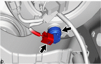
Disconnect the connector from the vacuum warning switch assembly.
-
Remove the vacuum warning switch assembly from the brake booster assembly.
-
Remove the check valve grommet from the brake booster assembly.
-