AIRBAG SYSTEM TC and CG Terminal Circuit
DESCRIPTION
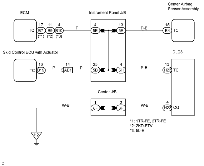
DTC output mode is set by connecting terminals TC and CG of the DLC3.
The DTCs are displayed by blinking the SRS warning light.
WIRING DIAGRAM
INSPECTION PROCEDURE
PROCEDURE
-
CHECK WIRE HARNESS (DLC3 - CENTER AIRBAG SENSOR ASSEMBLY)
-
Turn the ignition switch to the LOCK position.
-
Disconnect the connectors from the center airbag sensor assembly.
-
Measure the resistance according to the value(s) in the table below.
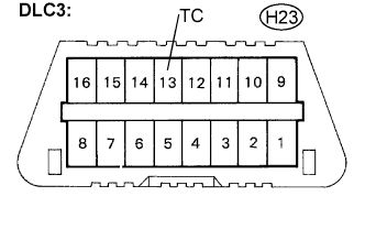
Resistance Tester connection Condition Specified condition H23-13 (TC) -
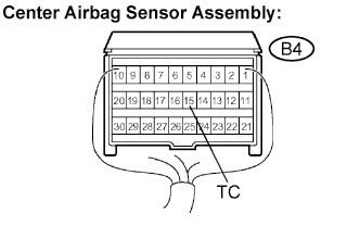
B4-15 (TC)
Always Below 1 Ω
NG 
REPAIR OR REPLACE WIRE HARNESS (TC OF DLC3 - TC OF CENTER AIRBAG SENSOR ASSEMBLY)
OK 
-
-
CHECK WIRE HARNESS (CG OF DLC3 - BODY GROUND)
-
Measure the resistance according to the value(s) in the table below.
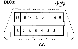
Resistance Tester connection Condition Specified condition H23-4 (CG) -
Body ground
Always Below 1 Ω
NG
REPAIR OR REPLACE WIRE HARNESS (CG OF DLC3 - BODY GROUND)
OK
-
-
CHECK WIRE HARNESS (TC OF CENTER AIRBAG SENSOR ASSEMBLY)
-
Measure the resistance according to the value(s) in the table below.
Resistance Tester connection Condition Specified condition B4-15 (TC) -
Body ground
Always 1 MΩ or higher
NG
REPAIR OR REPLACE WIRE HARNESS OR EACH ECU
OK 
REPLACE CENTER AIRBAG SENSOR ASSEMBLY
-