FRAME WIRE REMOVAL
PROCEDURE
-
REMOVE SERVICE PLUG GRIP
-
REMOVE CENTER FLOOR CARPET COVER LH
-
REMOVE CENTER FLOOR CARPET COVER RH
-
REMOVE UPPER CONSOLE PANEL SUB-ASSEMBLY
-
REMOVE FRONT NO. 2 CONSOLE BOX INSERT
-
REMOVE CONSOLE BOX ASSEMBLY
-
REMOVE NO. 1 HYBRID BATTERY SHIELD SUB-ASSEMBLY
-
REMOVE INVERTER WITH CONVERTER ASSEMBLY
-
REMOVE FRONT EXHAUST PIPE ASSEMBLY
-
REMOVE FRONT NO. 1 FLOOR HEAT INSULATOR
-
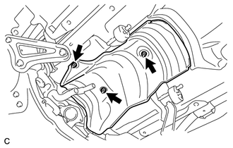
Remove the 3 nuts and front No. 1 floor heat insulator.
-
-
REMOVE FRONT SUSPENSION MEMBER REAR BRACE RH
-
Using a transmission jack, hold the front suspension cross member.
Note
Be sure to position the transmission jack to properly support the front suspension cross member.
-
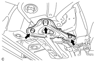
Remove the 3 bolts and front suspension member rear brace RH.
-
Temporarily install bolt A.
-
-
REMOVE TONNEAU COVER ASSEMBLY (w/ Tonneau Cover)
-
REMOVE REAR NO. 1 SEAT ASSEMBLY (for Side)
-
REMOVE REAR NO. 1 SEAT ASSEMBLY (for Center)
-
REMOVE REAR NO. 2 SEAT ASSEMBLY
-
REMOVE BACK DOOR SCUFF PLATE
-
DISCONNECT REAR NO. 1 SEAT OUTER BELT ASSEMBLY RH
Tech Tips
Use the same procedure as for the LH side Click here.
-
DISCONNECT REAR NO. 2 SEAT OUTER BELT ASSEMBLY RH
Tech Tips
Use the same procedure as for the LH side Click here.
-
REMOVE NO. 1 DECK TRIM COVER (for RH Side)
Tech Tips
Use the same procedure as for the LH side Click here.
-
REMOVE LUGGAGE HOLD BELT STRIKER ASSEMBLY (for RH Side)
Tech Tips
Use the same procedure as for the LH side Click here.
-
REMOVE FRONT DECK SIDE TRIM COVER RH
Tech Tips
Use the same procedure as for the LH side Click here.
-
REMOVE NO. 1 CUP HOLDER
-
REMOVE DECK TRIM SIDE PANEL ASSEMBLY RH
Tech Tips
Use the same procedure as for the LH side Click here.
-
DISCONNECT CABLE FROM POSITIVE AUXILIARY BATTERY TERMINAL
-
Remove the terminal cover.
-
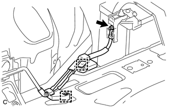
Disconnect the 2 clamps and remove the nut.
-
Disconnect the 2 clamps and disconnect the cable from positive auxiliary battery terminal.
-
-
DISCONNECT HYBRID BATTERY JUNCTION BLOCK ASSEMBLY
CAUTION:
Wear insulated gloves.
Note
Insulate the removed terminals with insulating tape.
-
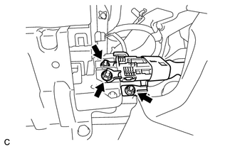
Remove the 3 nuts and disconnect the frame wire from the hybrid battery junction block assembly.
-
-
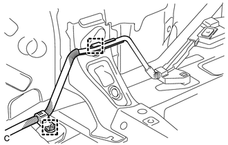
REMOVE FRAME WIRE
CAUTION:
Wear insulated gloves.
Note
Insulate the disconnected terminals with insulating tape.
-
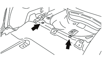
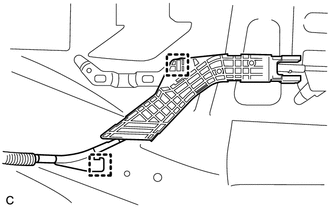
Remove the 2 clips.
-
Turn over the front floor carpet.
-
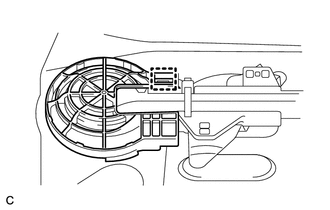
Disconnect the clamp and remove the wire harness protector from the floor panel.
-
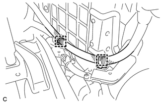
Disconnect the 2 wire harness clamps from the floor panel.
-
Disconnect the 2 clamps from the floor panel.
-
Disengage the 3 claws and push the frame wire out from the floor panel.
-
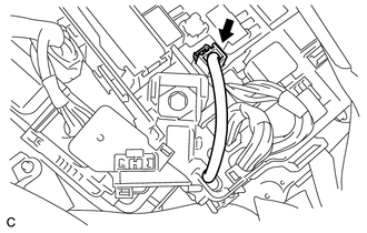
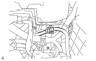
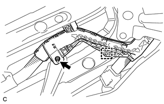
Disconnect the connector from the engine room junction block assembly.
-
Disconnect the 2 clamps.
-
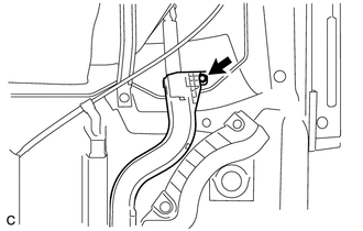
Disconnect the clamp.
-
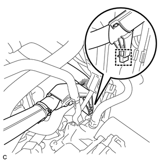
Disconnect the clamp.
-
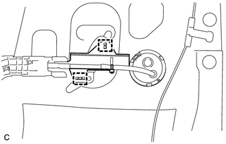
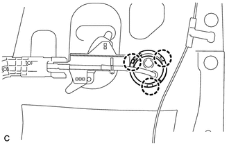
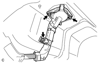
Remove the nut and separate the heater water pipe sub-assembly.
-
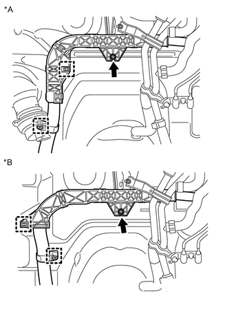
Text in Illustration *A for RHD: *B for LHD: Remove the nut and disconnect the 2 clamps.
-
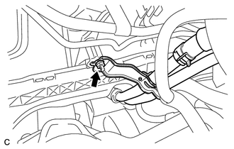
Remove the nut and disconnect the clamp.
-
Remove the bolt.
-
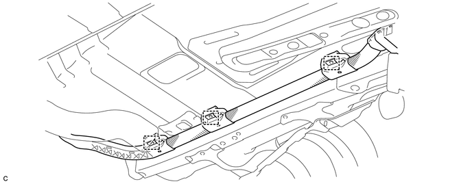
Remove the 3 nuts and frame wire out from the floor panel.
-
Disconnect the 3 clamps and remove the frame wire.
Note
The clamps are non-reusable parts.
-