KEY REMINDER WARNING SYSTEM TERMINALS OF ECU
CHECK INSTRUMENT PANEL JUNCTION BLOCK ASSEMBLY AND MAIN BODY ECU (MULTIPLEX NETWORK BODY ECU)
Remove the main body ECU (multiplex network body ECU).
for LHD:
for RHD:
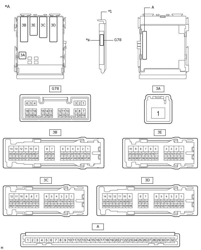
*A
Main body ECU (multiplex network body ECU) with 1 connector
-
-
*1
Main body ECU (multiplex network body ECU)
-
-
*a
1 connector
-
-
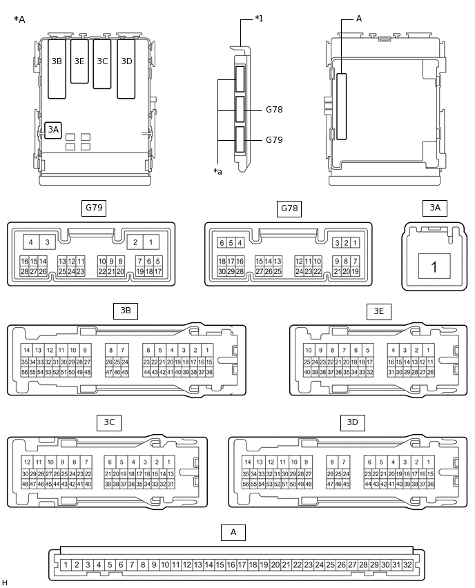
*A
Main body ECU (multiplex network body ECU) with 3 connectors
-
-
*1
Main body ECU (multiplex network body ECU)
-
-
*a
3 connectors
-
-
Measure the resistance according to the value(s) in the table below.
Tester Connection
Wiring Color
Terminal Description
Condition
Specified Condition
A-11 (GND1) - Body ground
-
Ground
Always
Below 1 Ω
A-2 (FLCY) - Body ground*1
-
Driver door courtesy light switch input
Driver door open
Below 1 Ω
A-2 (FLCY) - Body ground*1
-
Driver door courtesy light switch input
Driver door closed
10 kΩ or higher
G78-19 (FRCY) - Body ground*2
L - Body ground
Driver door courtesy light switch input
Driver door open
Below 1 Ω
G78-19 (FRCY) - Body ground*2
L - Body ground
Driver door courtesy light switch input
Driver door closed
10 kΩ or higher
G78-17 (KSW) - Body ground
R - Body ground
Unlock warning switch signal
No key in ignition key cylinder
10 kΩ or higher
G78-17 (KSW) - Body ground
R - Body ground
Unlock warning switch signal
Key in ignition key cylinder
Below 1 Ω
*1: for LHD
*2: for RHD
If the result is not as specified, there may be a malfunction on the wire harness side.