BRAKE CONTROL SYSTEM
-
FUNCTION OF MAIN COMPONENTS
Models without VSC Component Function Brake Actuator Assembly Solenoid Relay (Built into Skid Control ECU) Supplies power to the solenoid valves. Motor Relay (Built into Skid Control ECU) Supplies power to the pump motor. Solenoid Valves Change the fluid path based on the signals from the skid control ECU during the operation of the brake control system functions in order to control the fluid pressure applied to the wheel cylinders. Pump Motor Drives the pumps inside the brake actuator. Skid Control ECU Judges the vehicle driving condition based on the signals from each sensor and switch, and sends the brake control signals to the brake actuator. Speed Sensors Detect the wheel speed of each of the 4 wheels. Deceleration Sensor* Detects the vehicle's longitudinal acceleration and deceleration. Stop Light Switch Assembly Detects the brake pedal depressing signal. Parking Brake Switch Assembly Detects the parking brake lever status. Brake Fluid Level Warning Switch Detects the brake fluid level. Main Body ECU (Multiplex Network Body ECU) Transmits the parking brake switch signal to the skid control ECU. Combination Meter Assembly Brake Warning Light
-
Illuminates to alert the driver when the skid control ECU detects a malfunction in the EBD or brake system.
-
Illuminates to alert the driver when the brake fluid level is low.
-
Illuminates to inform the driver when the parking brake lever is pulled up.
ABS Warning Light Illuminates to alert the driver when the skid control ECU detects a malfunction in the ABS. Buzzer Emits a warning sound to alert the driver when the parking brake lever is pulled up.
-
*: 4WD/AWD Models
Models with VSC Component Function Brake Actuator Assembly Solenoid Relay (Built into Skid Control ECU) Supplies power to the solenoid valves. Motor Relay (Built into Skid Control ECU) Supplies power to the pump motor. Motor Cut Relay (Built into Skid Control ECU) Cuts the power to the pump motor when the motor relay malfunctions. Solenoid Valves Change the fluid path based on the signals from the skid control ECU during the operation of the brake control system functions in order to control the fluid pressure applied to the wheel cylinders. Pump Motor Drives the pumps inside the brake actuator. Master Cylinder Pressure Sensor Detects the master cylinder pressure. Speed Sensors Detect the wheel speed of each of the 4 wheels. Steering Sensor Detects the steering direction and angle of the steering wheel. Stop Light Switch Assembly Detects the brake pedal depressing signal. Parking Brake Switch Assembly Detects the parking brake lever status. Brake Fluid Level Warning Switch Detects the brake fluid level. VSC OFF Switch (Traction Control Switch) Enables the driver to select normal mode, TRC OFF mode or VSC OFF mode. Downhill Assist Control Switch*1 Allows the driver to turn downhill assist control on and off. Sport Mode Switch*2 Turns the Sport mode on and off. Skid Control ECU (Built into Brake Actuator Assembly)
-
Judges the vehicle driving condition based on the signals from each ECU, sensor and switch, and sends the brake control signals to the brake actuator.
-
Requests steering torque assist during cooperative control with EPS.
-
Requests torque distribution between the front and rear wheels during cooperative control with 4WD/AWD.*3
ECM
-
Outputs signals such as the shift position signal*4, Sport mode signal*4, throttle position signal and engine speed signal to the skid control ECU via CAN communication.
-
Controls the engine output based on the signals from the skid control ECU.
Power Steering ECU Assembly Operates in cooperation with the skid control ECU to control the steering assist torque. 4WD ECU Assembly*3
-
Operates in cooperation with the skid control ECU to control the torque distribution between the front and rear wheels.
-
Outputs Sport mode signals to the skid control ECU via CAN communication.*5
Center Airbag Sensor Assembly
-
Yawrate and Deceleration Sensor
Detects the vehicle's yaw rate, longitudinal and lateral acceleration, and sends the detection signals. Main Body ECU (Multiplex Network Body ECU) Outputs signals such as the parking brake signal to the skid control ECU via CAN communication. Engine Stop and Start ECU*6 Outputs signals such as the brake booster vacuum pressure signal to the skid control ECU via CAN communication. Combination Meter Assembly Brake Warning Light
-
Illuminates to alert the driver when the skid control ECU detects a malfunction in the EBD or brake system.
-
Illuminates to alert the driver when the brake fluid level is low.
-
Illuminates to inform the driver when the parking brake lever is pulled up.
ABS Warning Light Illuminates to alert the driver when the skid control ECU detects a malfunction in the ABS. Slip Indicator Light
-
Blinks to inform the driver when the Auto LSD*7, TRC, VSC, hill-start assist control or downhill assist control*1 is operational.
-
Illuminates to alert the driver when the skid control ECU detects a malfunction in the brake control function.
Auto LSD Indicator Light*7 Illuminates to inform the driver when Auto LSD is available. TRC OFF Indicator Light*3, *8 Illuminates to inform the driver when TRC OFF Mode or VSC OFF Mode is selected. VSC OFF Indicator Light Illuminates to inform the driver when VSC OFF Mode is selected. Downhill Assist Control Indicator Light*1 Illuminates to inform the driver when downhill assist control operation is possible. Sport Mode Indicator Light*2 Illuminates to inform the driver that Sport mode engaged. Multi-information Display*9
-
Displays a message to inform the driver when TRC OFF Mode is selected.*3
-
Displays a warning message to alert the driver when driving while the parking brake is applied.
Buzzer
-
Emits a warning sound to alert the driver when driving while the parking brake is applied.
-
Emits a warning sound to inform the driver when hill-start assist control operation is started or finished.
-
*1: Models with downhill assist control
-
*2: Except 2WD models with manual transaxle
-
*3: 4WD/AWD models
-
*4: Models with automatic transaxle or CVT
-
*5: Models with manual transaxle
-
*6: Models with stop and start system
-
*7: 2WD models
-
*8: Models with segment display type multi-information display
-
*9: Models with dot display type multi-information display
-
-
OPERATING CONDITION
-
Hill-start Assist Control
-
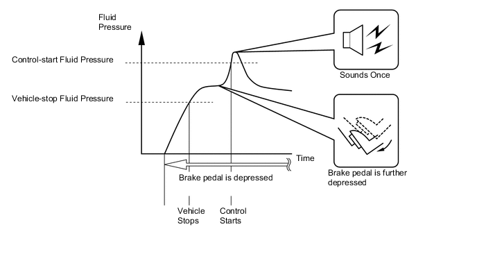
The skid control ECU starts hill-start assist control operation when the operating conditions below are met and the driver further depresses the brake pedal, causing the hydraulic pressure to exceed the control-start hydraulic pressure.
-
When hill-start assist control operation starts, the buzzer in the combination meter assembly will sound once.
Hill-start Assist Control Operation Condition
-
The shift lever is in any position other than P.
-
The accelerator pedal is not depressed.
-
The vehicle is at a standstill.
-
The parking brake is not applied.
-
-
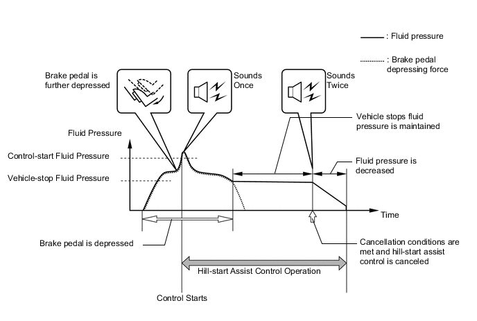
If any one of the conditions below is met during hill-start assist control operation, hill-start assist control will be canceled causing the slip indicator light to turn off.
-
The buzzer in the combination meter assembly sounds twice if the hill-start assist control is canceled.
Conditions which cause hill-start assist control operation to be canceled. Buzzer in combination meter assembly does not sound. The driver depresses the accelerator pedal. Buzzer in combination meter assembly sounds twice.
-
The driver moves the shift lever to P.
-
The driver depresses the parking brake pedal.
-
The driver depresses the brake pedal.
-
The driver releases the brake pedal for several seconds.
-
The driver keeps the brake pedal depressed continually for 3 minutes.
Figure 1. Hill-start assist control is canceled without buzzer in combination meter assembly sounding
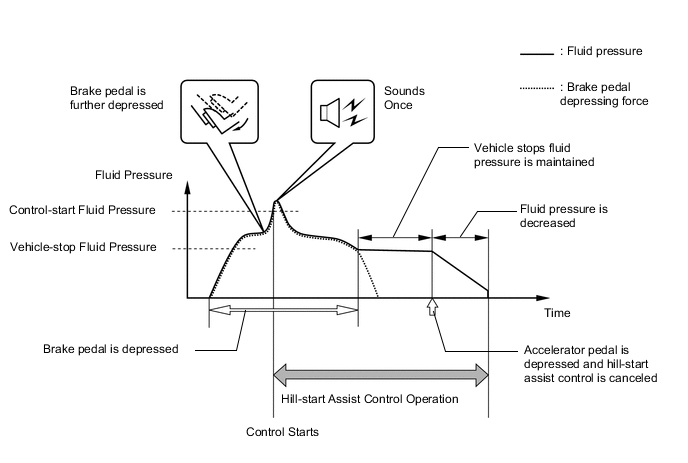
Figure 2. Hill-start assist control is canceled with buzzer in combination meter assembly sounding twice
-
-
-
Downhill Assist Control
-
The downhill assist control operates when all of the following conditions have been met:
Downhill Assist Control Operation Condition
-
Downhill assist control switch is on.
-
Shift range is in M1*1, S1*2 or R.
-
Accelerator pedal and brake pedal are not depressed.
-
Vehicle is descending down a hill at a vehicle speed of 25 km/h (16 mph) or less.
-
VSC OFF indicator light is not illminated.
-
*1: Except models with 2AR-FE engines
-
*2: Models with 2AR-FE engines
-
-
-
-
SYSTEM CONTROL
Electronic Control of Brake Control System Control Outline Anti-lock Brake System (ABS) The ABS helps prevent the wheels from locking when the brakes are applied firmly or when braking on a slippery surface. Electronic Brake Force Distribution (EBD) The EBD control utilizes ABS, achieving proper brake force distribution between the front and rear wheels in accordance with the driving conditions. In addition, during braking while cornering, the EBD also controls the brake forces of the right and left wheels, helping maintain vehicle behavior. Brake Assist The primary purpose of brake assist is to provide an auxiliary brake force to assist a driver who cannot generate a large brake force during emergency braking, thus helping ensure the vehicle's braking performance.
If the brake booster malfunctions and the skid control ECU judges that the brake pedal force applied by the driver is not sufficient to ensure adequate braking force, brake assist is used to enhance the braking force.
Auto LSD The Auto LSD uses a TRC to achieve Limited Slip Differential (LSD) capability. The Auto LSD allows for greater traction control than the TRC, ensuring startability and traction on sand or other road surfaces that present high degrees of drive resistance. Traction Control (TRC) The TRC helps restrain the slippage of the drive wheels if the driver depresses the accelerator pedal excessively when starting off or accelerating on a slippery surface. Vehicle Stability Control (VSC) The VSC helps restrain sideways slippage of the vehicle during a strong front wheel skid or a strong rear wheel skid, such as may occur while cornering. Cooperative Control with Electric Power Steering (EPS) This performs cooperative control with the power steering ECU assembly in order to provide steering assist in accordance with the operating conditions of the vehicle. Cooperative Control with 4WD/AWD System This performs cooperative control with the 4WD ECU assembly in order to control the drive torque of the front and rear wheels in accordance with the operating conditions of the vehicle. Hill-start Assist Control When starting uphill, the hill-start assist control maintains the brake hydraulic pressure to the 4 wheels in order to momentarily prevent the vehicle from descending backward. Downhill Assist Control The downhill assist control is used when driving downhill on a sharp slope on which the engine brake alone will not adequately decelerate the vehicle. The driver can operate the downhill assist control switch while the shift range is in M1 *1, S1*2 or R, in order to automatically control the brake hydraulic pressure to the four wheels.
-
*1: Except models with 2AR-FE engines
-
*2: Models with 2AR-FE engines
-
Anti-lock Brake System (ABS)
-
The ABS prevents the wheels from locking during sudden braking or braking on a slippery surface. The ABS provides the proper braking force when the vehicle slips, thus ensuring vehicle stability and excellent braking performance.
*A With ABS *B Without ABS *a Brake Operation - -
-
-
Electronic Brake Force Distribution (EBD)
-
The EBD controls the brake force that acts on the rear wheels in accordance with the changes in the vehicle conditions such as load factors or deceleration in order to ensure excellent braking performance.
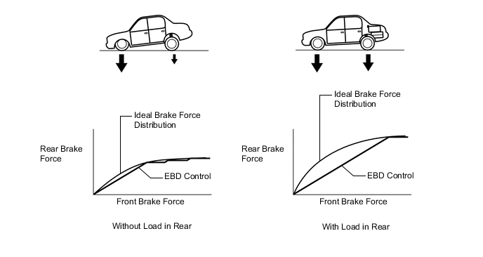
-
During braking while cornering, this function controls the brake force that acts on the left and right wheels in accordance with the vehicle conditions at that time. This ensures vehicle stability and excellent braking performance.


Brake Force 
Control Moment
-
-
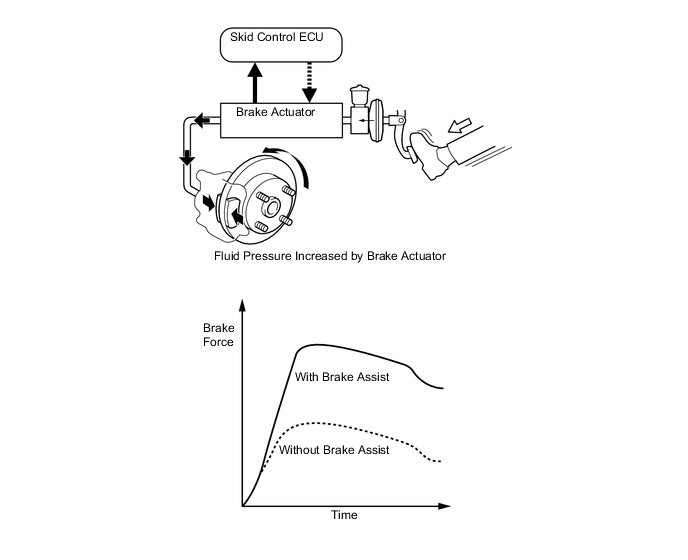
Brake Assist
-
In the brake assist, the skid control ECU calculates the speed and the amount of the brake pedal application based on the signals from the master cylinder pressure sensor and then determines the intention of the driver to make an emergency brake application. If the skid control ECU determines that the driver intends to make an emergency brake application, this function activates the brake actuator to increase the brake fluid pressure, which increases the brake force.
-
-
Auto LSD
-
The Auto LSD achieves the equivalent functions of a Limited Slip Differential (LSD) through the use of a traction control function. For this reason, the contents of the brake control are the same in both the Auto LSD and TRC. When the driver presses the Auto LSD switch, this function achieves the LSD effect by regulating the hydraulic pressure that acts on the drive wheels and controlling the engine output in accordance with the amount of pedal effort applied on the accelerator.
-
The TRC enhances the start-off performance of the vehicle during low-resistance surface conditions, such as snow or mud, by restricting the acceleration effort during a start-off in order to prevent the wheels from spinning.
-
On the other hand, the Auto LSD tends to enhance the acceleration effort somewhat in order to apply greater drive torque to the wheel when it is in contact with the ground. Thus, this function helps the vehicle to become unstuck if a wheel loses its grip, and enhances the vehicle's start-off performance on high-resistance surface such as gravel roads.
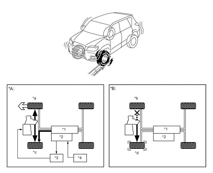
*A With Auto LSD *B Without Auto LSD *1 Brake Actuator *2 Skid Control ECU *3 ECM *4 VSC OFF Switch *a Traction *b No Traction *c Braking *d Slipping
-
-
Traction Control (TRC)
-
The TRC helps prevent the drive wheels from slipping if the driver depresses the accelerator pedal excessively when starting off or accelerating on a slippery surface. Simultaneously with the hydraulic brake control of the drive wheels, the skid control ECU makes a request to the ECM to effect engine output control. This produces the drive force that suits the driving conditions in order to ensure the proper start-off acceleration.
*A Without TRC *B With TRC *C 4WD/AWD Models - - *1 Engine *2 ECM *3 Skid Control ECU *4 Brake Actuator *a Slippery Surface *b Engine Output Control *c Brake Slipping Drive Wheel - -
-
-
Vehicle Stability Control (VSC)
-
The following are 2 examples that can be considered circumstances in which the tires exceed their lateral grip limit. The VSC is designed to help control the vehicle behavior by controlling the engine output and the brakes at each wheel when the vehicle is under one of the conditions indicated below:
*a Front Wheel Skid Tendency *b Rear Wheel Skid Tendency -
To determine the condition of the vehicle, sensors detect the steering angle, vehicle speed, vehicle's yaw rate and vehicle's lateral acceleration, which are then calculated by the skid control ECU.
-
Whether or not the vehicle is experiencing a front wheel skid is determined by the difference between the target yaw rate and the vehicle's actual yaw rate. When the vehicle's actual yaw rate is smaller than the target yaw rate (a target yaw rate is determined based on the vehicle speed and steering angle) that should be generated when the driver operates the steering wheel, it means the vehicle is making a turn at a greater angle than the target locus of travel. Thus, the skid control ECU determines that there is a large front wheel skid tendency.
*a Actual Locus of Travel (Actual Yaw Rate) *b Locus of Travel Based on Target Yaw Rate -
Whether or not the vehicle is experiencing a rear wheel skid is determined by the values of the vehicle's slip angle and the vehicle's slip angular velocity (time-dependent changes in the vehicle's slip angle). When the vehicle's slip angle is large and the slip angular velocity is also large, the skid control ECU determines that the vehicle has a large rear wheel skid tendency.

*a Direction of Travel of Vehicle's Center of Gravity *b Movement of Vehicle Slip Angle - - -
When the skid control ECU determines that the vehicle exhibits a tendency to experience a front wheel skid or a rear wheel skid, it decreases the engine output and applies the brakes of the front or rear wheels to control the vehicle's yaw moment. The basic operation of the VSC is described below. However, the control method differs depending on the vehicle's characteristics and driving conditions.
-
When the skid control ECU determines that there is a large front wheel skid tendency, it takes countermeasures in accordance with the extent of that tendency. The skid control ECU controls the engine output and applies the brakes of the front wheels and the rear wheel on the inner circle of the turn in order to help restrain the front wheel skid tendency.
Figure 3. Front Wheel Skid Tendency

*a Making a Right Turn - - Brake Force Control Moment -
When the skid control ECU determines that there is a large rear wheel skid tendency, it takes countermeasures in accordance with the extent of that tendency. The skid control ECU applies the brakes of the wheels on the outer circle of the turn and generates an outward moment of inertia in the vehicle in order to restrain the rear wheel skid tendency. Along with the reduction in the vehicle speed caused by the braking force, excellent vehicle stability is ensured.
Figure 4. Rear Wheel Skid Tendency

*a Making a Right Turn - - Brake Force Control Moment
-
-
Cooperative Control with EPS
-
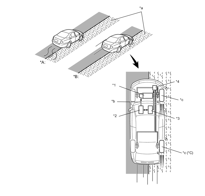
Braking when Surface Resistance Differs between Both Sides of Wheels
-
If the driver suddenly applies the brakes on a road surface with a considerable difference in friction coefficient between the right and left wheels, the difference in the brake force between the right and left wheels will cause the vehicle posture to become unstable and create a yaw moment. In this state, the skid control ECU controls the VSC to stabilize the vehicle posture. At the same time, the skid control ECU performs cooperative control with the EPS to provide steering torque assist, which facilitates the driver's steering maneuvers to stabilize the vehicle posture.
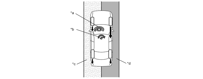
*a Assist Direction *b Yaw Moment during Brake Control *c Low μ Road *d High μ Road Brake Force - - -
-
Accelerating when Surface Resistance Differs between Both Sides of Wheels
-
If the driver suddenly starts off or accelerates on a road surface with a considerable difference in friction coefficient between the right and left wheels, the slippage of a drive wheel will cause the vehicle posture to become unstable and negatively affect its acceleration performance. In this state, the skid control ECU causes the TRC to control the hydraulic brake of the slipping drive wheel, and requests the ECM to effect engine output control. At the same time, the skid control ECU performs cooperative control with the EPS to provide steering torque assist, which facilitates the driver's steering maneuvers to stabilize the vehicle posture.
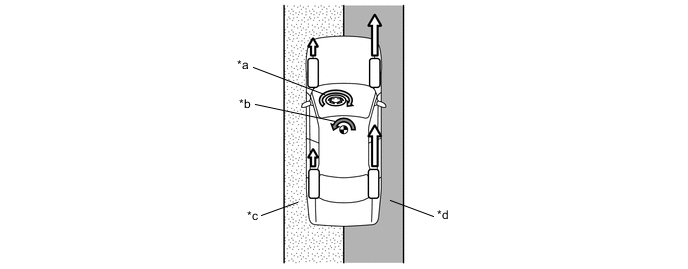
*a Assist Direction *b Yaw Moment during Acceleration *c Low μ Road *d High μ Road Drive Force - - -
-
Front Wheel Skid Tendency
-
When the skid control ECU determines a front wheel skid tendency, it controls the VSC to dampen the front wheel skid. At the same time, the skid control ECU performs the cooperative control with the EPS to provide steering torque assists, which controls the driver's steering maneuvers to stabilize the vehicle posture. Steering torque assists are provided to inform the driver of the front wheel skid (a), and to prevent the driver's excessive turning of the steering wheel (b). In the assist for preventing excessive turning (b), the skid control ECU increases the resistance to counter the driver's steering effort, if the driver turns the steering wheel excessively.
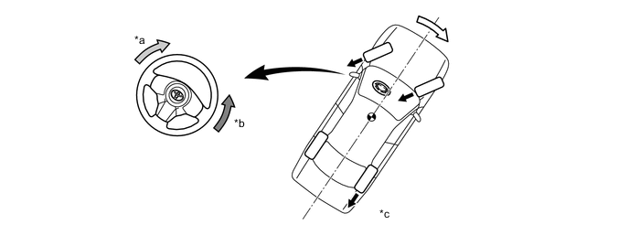
*a (a) Assist Direction for Informing Driver of Front Wheel Skid *b (b) Assist Direction for Preventing Excessive Turning *c Making a Right Turn - - Brake Force Control Moment -
-
Rear Wheel Skid Tendency
-
When the skid control ECU determines a rear wheel skid tendency, it controls the VSC to dampen the rear wheel skid. At the same time, the skid control ECU performs cooperative control with the EPS to provide steering torque assist, which facilitates the driver's steering maneuvers in the direction to correct the rear wheel skid.
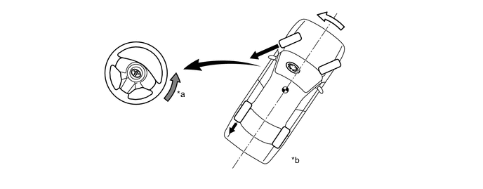
*a Assist Direction *b Making a Right Turn Brake Force Control Moment -
-
-
Cooperative Control with 4WD/AWD System
-
Acceleration During Cornering
-
A sudden acceleration of the vehicle during cornering may cause a drive wheel to freewheel, which could cause the front wheels or rear wheels to skid. If the skid control ECU determines the freewheeling of a drive wheel, a front wheel skid tendency or a rear wheel skid tendency, it performs cooperative control with the 4WD/AWD system to optimally control the drive torque distribution to the front and rear wheels. Furthermore, the skid control ECU controls the TRC and the VSC as needed to ensure driving stability and acceleration performance.

*a Making a Right Turn - - Drive Torque Distribution to Rear Wheel Drive Force Figure 5. Rear Wheel Skid Tendency

*a Making a Right Turn - - Drive Torque Distribution to Rear Wheel Drive Force -
-
-
Hill-start Assist Control
-
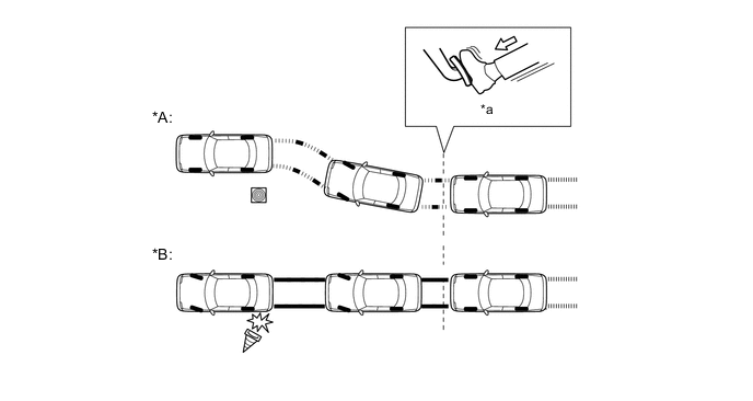
When the vehicle starts off on a steep or slippery hill, it could descend backward while the driver switches from the brake pedal to the accelerator pedal, thus making it difficult for the vehicle to start off. To prevent this from occurring, the hill-start assist control temporarily (approximately 2 seconds at the maximum) applies the brakes to all the wheels in order to prevent the vehicle from descending backward.
-
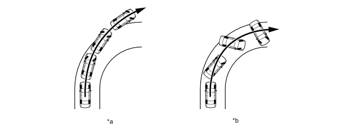
Without the hill-start assist control, the driver must quickly and precisely switch from the brake pedal to the accelerator pedal. With the hill-start assist control, however, the driver can start off easily and operate the pedal in a relaxed manner because the hill-start assist control prevents the vehicle from descending backward.
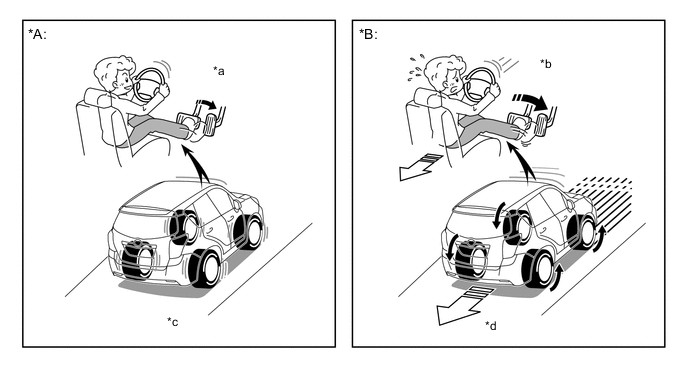
*A With Hill-start Assist Control *B Without Hill-start Assist Control *a Easy Control *b Difficult Control *c Prevent Vehicle from Descending Backward *d Increase Backward Speed of Vehicle
-
-
Downhill Assist Control
-
When the vehicle is descending a steep hill and engine brake alone cannot provide a sufficient deceleration force while the transaxle is in the L or R range, the downhill assist control performs 4-wheel brake control to maintain a constant, low vehicle speed. Thus, the vehicle is able to descend in a stable manner without causing the wheels to become locked.
-
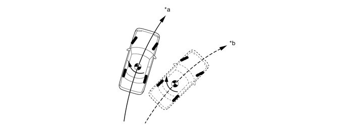
When the vehicle descends a steep hill without the downhill assist control, the driver must pay close attention to the brake and accelerator pedal operations. However, with the downhill assist control, the driver can concentrate on the steering operation without accelerator and brake pedal operations.
-
The downhill assist control enables the vehicle to achieve a high level of stability because it can descend a slippery hill at low speeds without causing the wheels to become locked.
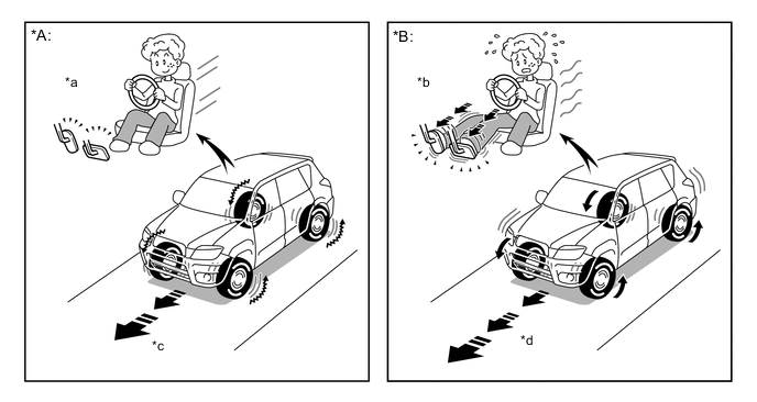
*A With Downhill Assist Control *B Without Downhill Assist Control *a Easy Control (No Braking and No Accelerating) *b Difficult Control *c Stable Speed *d Unstable Speed
-
-
-
FAIL-SAFE
-
If a failure occurs in the skid control ECU, sensors or brake actuator assembly, the system continues effecting brake control by excluding the failed area and using only the areas that are operating normally.
-
-
DIAGNOSIS
-
If the skid control ECU detects a malfunction in the brake control system, the warning lights or indicator light illuminate. At the same time, a Diagnostic Trouble Code (DTC) is stored in the memory of the skid control ECU.
-
This system has a sensor signal check (test mode) function.
-
For details of DTCs and check function, refer to the Repair Manual.
-