CAN COMMUNICATION SYSTEM(w/o Central Gateway ECU) SYSTEM DIAGRAM
-
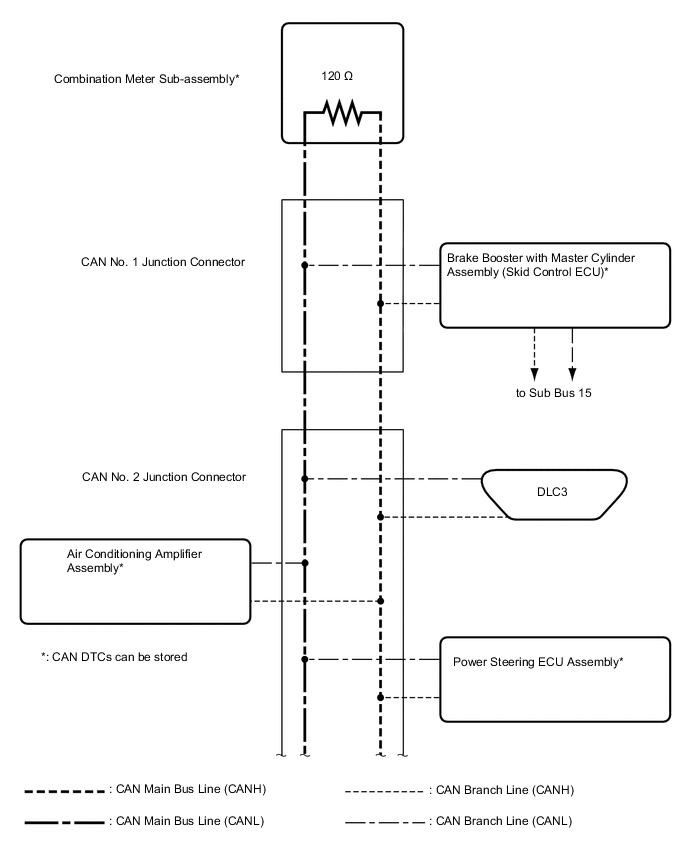
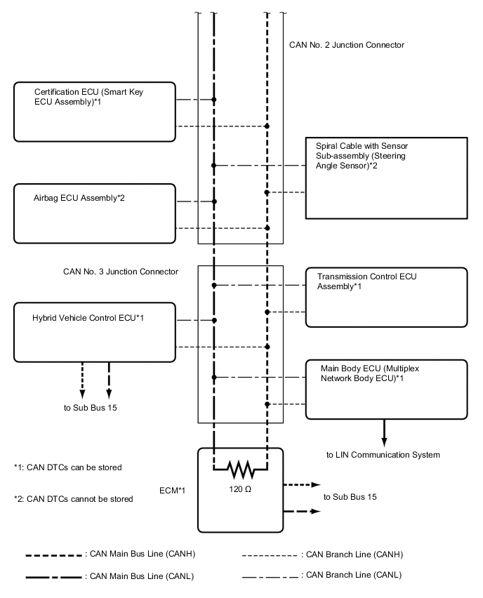
OVERALL CAN BUS DIAGRAM
-
The CAN communication system is composed of 2 buses.
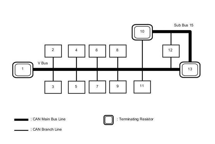
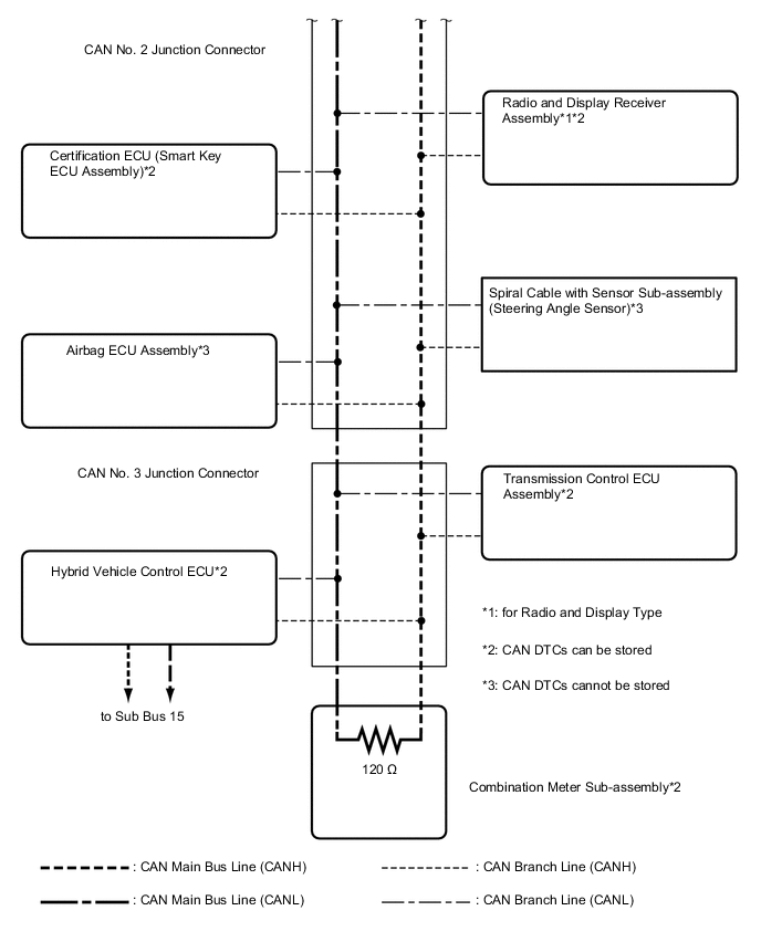
1 Combination Meter Sub-assembly
(for V Bus)
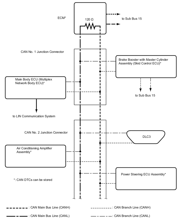
2 Main Body ECU (Multiplex Network Body ECU)
(for V Bus)
3 DLC3
(for V Bus)
4 Airbag ECU Assembly
(for V Bus)
5 Spiral Cable with Sensor Sub-assembly (Steering Angle sensor)
(for V Bus)
6 Power Steering ECU Assembly
(for V Bus)
7 Certification ECU (Smart Key ECU Assembly)
(for V Bus)
8 Air Conditioning Amplifier Assembly
(for V Bus)
9 Radio and Display Receiver Assembly
(for Radio and Display Type)
(for V Bus)
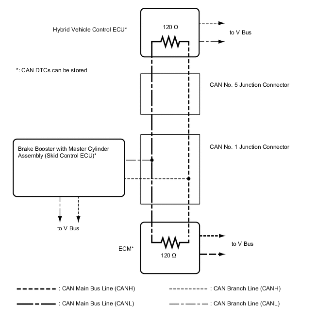
10 Hybrid Vehicle Control ECU
(for V Bus and Sub Bus 15)
11 Transmission Control ECU Assembly
(for V Bus)
12 Brake Booster with Master Cylinder Assembly (Skid Control ECU)
(for V Bus and Sub Bus 15)
13 ECM
(for V Bus and Sub Bus 15)
- - Tech Tips
Refer to the following bus wiring diagrams for details.
-
-
V BUS (for LHD)
Tech Tips
The CAN communication system connects to other networks via ECUs that function as a gateway Click here.
-
V BUS (for RHD)
Tech Tips
The CAN communication system connects to other networks via ECUs that function as a gateway Click here.
-
SUB BUS 15