NAVIGATION SYSTEM Pointer Displayed/not Displayed Repeatedly
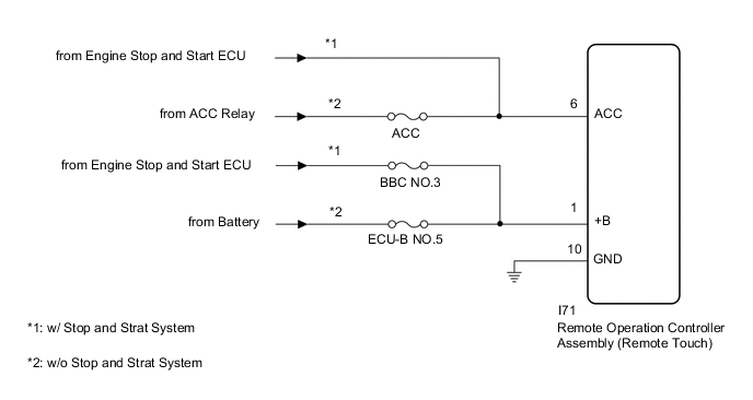
WIRING DIAGRAM
CAUTION / NOTICE / HINT
Note
Inspect the fuses for circuits related to this system before performing the following procedure.
PROCEDURE
-
CONFIRM SYMPTOMS
-
Recheck the situation when the malfunction occurs.
Tech Tips
-
When a hand is rested on the remote touch screen while driving, the remote touch may react to finger movements and repeatedly display and hide the pointer.
-
When accelerating excessively on rough roads, the remote touch may react to the acceleration and repeatedly display and hide the pointer.
Result Result Proceed to Symptom occurs in any situation. A Symptom occurs when hand is rested on the remote touch screen while driving. B Symptom occurs when accelerating excessively on rough roads. C -
B 
END
C 
CHECK CONNECTOR CONNECTION CONDITION Click here
A 
-
-
CHECK FOR FOREIGN MATTER
-
Check if there is any foreign matter around the remote touch screen that interferes with operation of the screen.
OK There is no foreign matter around the remote touch screen that interferes with operation of the screen. Result Proceed to OK NG
OK
USE SIMULATION METHOD TO CHECK Click here
NG
REMOVE FOREIGN MATTER (CHECK OPERATION AGAIN)
-
-
CHECK CONNECTOR CONNECTION CONDITION
-
Check if the I71 remote operation controller assembly (remote touch) connector is securely connected.
OK The connector is securely connected. Result Proceed to OK NG
NG
SECURELY CONNECTED
OK
-
-
CHECK HARNESS AND CONNECTOR (REMOTE OPERATION CONTROLLER ASSEMBLY [REMOTE TOUCH] - BATTERY AND BODY GROUND)
-
Disconnect the remote operation controller assembly (remote touch) connector.
-
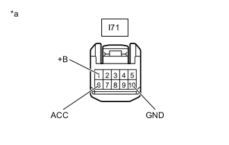
*a Front view of wire harness connector
(to Remote Operation Controller Assembly [Remote Touch])
Measure the resistance according to the value(s) in the table below.
Standard Resistance Tester Connection Condition Specified Condition I71-10 (GND) - Body ground Always Below 1 Ω -
Measure the voltage according to the value(s) in the table below.
Standard Voltage Tester Connection Condition Specified Condition I71-1 (+B) - Body ground*1 Always 11 to 14 V I71-1 (+B) - Body ground*2 Always 10.5 to 16 V I71-6 (ACC) - Body ground*1 Engine switch on (ACC) 11 to 14 V I71-6 (ACC) - Body ground*2 Engine switch on (ACC) 10.5 to 16 V
-
*1: w/o Stop and Start System
*2: w/ Stop and Start System
Result Proceed to OK NG -
OK
REPLACE REMOTE OPERATION CONTROLLER ASSEMBLY (REMOTE TOUCH) Click here
NG
REPAIR OR REPLACE HARNESS OR CONNECTOR
-