VEHICLE STABILITY CONTROL SYSTEM AUTO LSD Indicator Light Remains ON
| DTC Code | DTC Name |
|---|---|
| AUTO LSD Indicator Light Remains ON |
DESCRIPTION
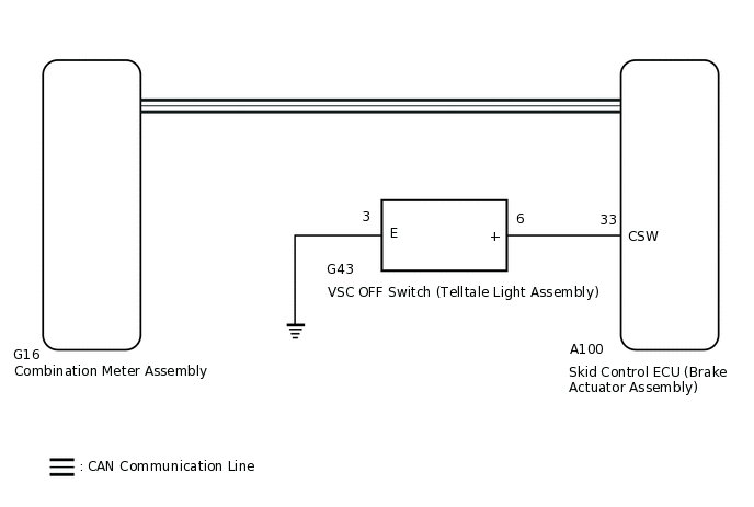
The AUTO LSD is a system for 2WD vehicles. When the VSC OFF switch (telltale light assembly) is pushed on, the AUTO LSD function is available and the AUTO LSD indicator light illuminates.
The AUTO LSD does not operate even if the VSC OFF switch (telltale light assembly) is pressed under the following conditions:
The TRC/TRAC or VSC system is faulty.
The temperature inside the brake actuator assembly increases and the AUTO LSD operation is suspended.
WIRING DIAGRAM
CAUTION / NOTICE / HINT
When replacing the skid control ECU (brake actuator assembly), perform zero point calibration.
PROCEDURE
CHECK IF SKID CONTROL ECU CONNECTOR IS SECURELY CONNECTED
Check if the skid control ECU (brake actuator assembly) connector is securely connected.
OK
The connector is securely connected.
Result
Proceed to
OK
NG
NG CONNECT CONNECTOR TO ECU CORRECTLY
CHECK CAN COMMUNICATION SYSTEM
Check if CAN communication system DTCs are output.
for LHD with Central Gateway ECU:Click here
for RHD with Central Gateway ECU:Click hereClick here
for LHD without Central Gateway ECU:Click here
for RHD without Central Gateway ECU:Click here
Result
Proceed to
DTC is not output
DTC is output (for LHD with Central Gateway ECU)
DTC is output (for RHD with Central Gateway ECU)
DTC is output (for LHD without Central Gateway ECU)
DTC is output (for RHD without Central Gateway ECU)
CHECK HARNESS AND CONNECTOR (CSW TERMINAL)
Turn the ignition switch off.
Disconnect the A100 skid control ECU (brake actuator assembly) connector.
-
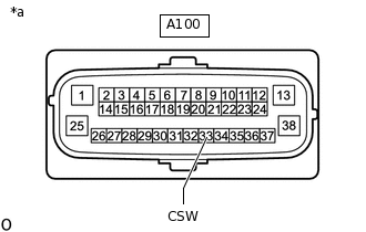
*a
Front view of wire harness connector
(to Skid Control ECU [Brake Actuator Assembly])
Measure the resistance according to the value(s) in the table below.
Standard Resistance
Tester Connection
Switch Condition
Specified Condition
A100-33 (CSW) - Body ground
VSC OFF switch (telltale light assembly) held on
Below 1 Ω
VSC OFF switch (telltale light assembly) off (Not pressed)
10 kΩ or higher
Result
Proceed to
OK
NG
NG INSPECT TELLTALE LIGHT ASSEMBLYClick here
READ VALUE USING GTS (AUTO LSD INDICATOR LIGHT)
Reconnect the A100 skid control ECU (brake actuator assembly) connector.
Connect the GTS to the DLC3.
Turn the ignition switch to ON.
Turn the GTS on.
Enter the following menus: Chassis / ABS/VSC/TRC / Data List.
According to the display on the GTS, read the Data List.
Check the GTS display condition of the AUTO LSD indicator light.
Chassis > ABS/VSC/TRC > Data List
Tester Display
Measurement Item
Range
Normal Condition
Diagnostic Note
Auto LSD Indicator Light
AUTO LSD indicator light
ON or OFF
OFF: AUTO LSD indicator light off
ON: AUTO LSD indicator light on
for 2WD
Chassis > ABS/VSC/TRC > Data List
Tester Display
Auto LSD Indicator Light
Result
Proceed to
Display of the Data List remains OFF
Display of the Data List remains ON
INSPECT TELLTALE LIGHT ASSEMBLY
Remove the VSC OFF switch (telltale light assembly).
Inspect the VSC OFF switch (telltale light assembly).
Result
Proceed to
OK
NG
CHECK HARNESS AND CONNECTOR (BRAKE ACTUATOR ASSEMBLY - TELLTALE LIGHT ASSEMBLY)
Measure the resistance according to the value(s) in the table below.
Standard Resistance
Tester Connection
Condition
Specified Condition
A100-33 (CSW) - G43-6 (+)
Always
Below 1 Ω
G43-13 (E) - Body ground
Always
Below 1 Ω
A100-33 (CSW) or G43-6 (+) - Body ground
Always
10 kΩ or higher
Result
Proceed to
OK
NG
NG REPAIR OR REPLACE HARNESS OR CONNECTOR