BRAKE MASTER CYLINDER(for LHD) INSTALLATION
PROCEDURE
INSTALL BRAKE MASTER CYLINDER SUB-ASSEMBLY
Note:When installing a new brake master cylinder sub-assembly, remove the protectors from the master cylinder piston and outlet ports.
-
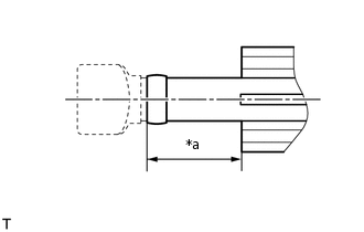
*a
More than 22 mm (0.866 in.)
for Manual Transaxle:
When installing a new brake master cylinder reservoir assembly or a new brake master cylinder sub-assembly, cut off the clutch tube tip of the brake master cylinder reservoir assembly as shown in the illustration.
CAUTION:Be careful not to cut your finger on the cut surface.
Note:Do not allow any foreign matter to enter the brake master cylinder reservoir assembly.
Make sure that fluid supply is not affected by cutting the tube.
Install a new brake master cylinder O-ring to the brake master cylinder sub-assembly.
-
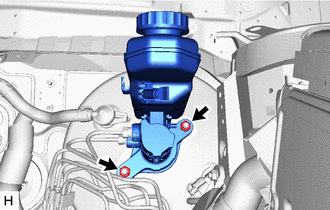
Install the brake master cylinder sub-assembly to the brake booster assembly with the 2 nuts.
20 N*m
204 kgf*cm
15 ft.*lbf
Note:Do not hold the brake master cylinder sub-assembly by the master cylinder piston. Hold the brake master cylinder sub-assembly by its body or its reservoir when carrying it.
Do not pull out the master cylinder piston.
Do not strike or pinch the master cylinder piston and do not cause any damage to the master cylinder piston by any other means.
When installing the brake master cylinder sub-assembly to the brake booster assembly, or when removing the brake master cylinder sub-assembly from the brake booster assembly, make sure that the brake master cylinder sub-assembly is kept horizontal or with its tip facing downward (the master cylinder piston is facing upward) to prevent the master cylinder piston from falling out.
Do not allow any foreign matter to contaminate the master cylinder piston. If any foreign matter gets on the master cylinder piston, remove it by using a piece of cloth and then apply an even layer of lithium soap base glycol grease around the circumference (sliding part) of the master cylinder piston.
Do not kink or damage the brake lines.
Do not allow the brake lines to twist and interfere with other parts or vehicle body during tightening.
Do not allow any foreign matter such as dirt or dust to enter the brake lines.
-
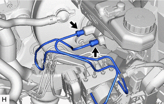
Using a union nut wrench, connect the 2 brake lines to the brake master cylinder sub-assembly.
w/o VSC
15.2 N*m
155 kgf*cm
11 ft.*lbf
w/ VSC
19.5 N*m
199 kgf*cm
14 ft.*lbf
Note:Do not kink or damage the brake lines.
Do not allow any foreign matter such as dirt or dust to enter the brake lines.
Use the formula to calculate special torque values for situations where the union nut wrench is combined with a torque wrench.
-
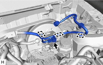
Connect the reservoir level switch connector and engage the 3 clamps.
-
CONNECT CLUTCH RESERVOIR TUBE (for Manual Transaxle)
Connect the clutch reservoir tube to the brake master cylinder sub-assembly and slide the clip to secure it.
BLEED BRAKE SYSTEM
BLEED CLUTCH LINE (for Manual Transaxle)
INSTALL FUEL FILTER SUPPORT (for 1AD-FTV, 1ND-TV)
INSTALL GLOW PLUG RELAY ASSEMBLY (for 1AD-FTV, 1ND-TV)
CONNECT WIRE HARNESS (for 1AD-FTV, 1ND-TV)
INSTALL FUEL FILTER ASSEMBLY (for 1AD-FTV, 1ND-TV)
for 1AD-FTV:Click here
for 1ND-TV:Click here
INSTALL AIR CLEANER CASE SUB-ASSEMBLY (for 1NR-FE)
INSTALL AIR CLEANER CAP SUB-ASSEMBLY (for 1NR-FE)
INSTALL NO. 1 ENGINE COVER (for 1NR-FE)
INSTALL AIR CLEANER CASE SUB-ASSEMBLY (for 1ZR-FAE)
INSTALL AIR CLEANER CAP SUB-ASSEMBLY (for 1ZR-FAE)
INSTALL NO. 2 CYLINDER HEAD COVER (for 1ZR-FAE)
INSTALL AIR CLEANER CASE SUB-ASSEMBLY (for 1AD-FTV)
INSTALL AIR CLEANER CAP SUB-ASSEMBLY (for 1AD-FTV)
INSTALL NO. 1 ENGINE COVER (for 1AD-FTV)
INSTALL AIR CLEANER CASE SUB-ASSEMBLY (for 1ND-TV)
INSTALL AIR CLEANER CAP SUB-ASSEMBLY (for 1ND-TV)
INSTALL NO. 1 ENGINE COVER (for 1ND-TV with No. 1 Engine Cover)
INSTALL OUTER COWL TOP PANEL
-
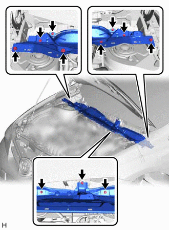
Install the outer cowl top panel with the 11 bolts.
12 N*m
122 kgf*cm
9 ft.*lbf
-
INSTALL DIFFERENTIAL PRESSURE SENSOR ASSEMBLY (for 1AD-FTV)
-
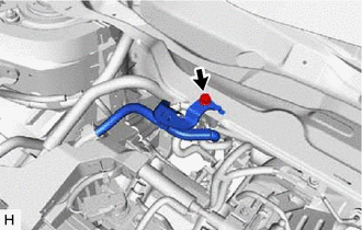
Install the differential pressure sensor assembly to the outer cowl top panel with the bolt.
8.0 N*m
82 kgf*cm
71 in.*lbf
-
INSTALL NO. 2 HEATER AIR DUCT SPLASH SHIELD SEAL
-
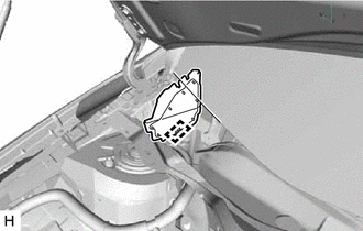
Engage the clamp to install the No. 2 heater air duct splash shield seal.
-
INSTALL WATER GUARD PLATE LH
-
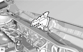
Engage the clamp to install the water guard plate LH.
-
INSTALL WINDSHIELD WIPER MOTOR AND LINK ASSEMBLY
BLEED AIR FROM FUEL SYSTEM (for 1AD-FTV, 1ND-TV)
for 1AD-FTV:Click here
for 1ND-TV:Click here
INSPECT FOR FUEL LEAK (for 1AD-FTV, 1ND-TV)
for 1AD-FTV:Click here
for 1ND-TV:Click here