FRONT LOWER SUSPENSION ARM (for 2WD) INSTALLATION
Tech Tips
-
Use the same procedure for the RH and LH sides.
-
The procedure listed below is for the LH side.
-
INSTALL LOWER BALL JOINT ASSEMBLY
-
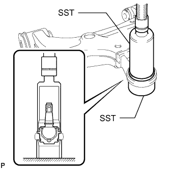
Using SST and press, press in a new lower ball joint.
- SST
- 09226-10010
- 09631-32020
-
Install a new snap ring.
Note
Make sure the snap ring is securely installed in the groove.
-
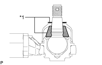
Text in Illustration *1 MP Grease No. 2 Pack the upper ball joint with MP grease No. 2.
Grease capacity 8.0 g (0.282 oz.) -
Apply MP grease No. 2 to the locations shown in the illustration.
Note
Do not apply MP grease No. 2 to the tapered or threaded parts of the ball joint.
-
Install a new dust cover to the lower arm.
-
Install a new dust cover set ring.
-
-
INSTALL FRONT NO. 2 LOWER ARM BUSH
-
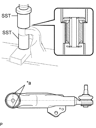
Text in Illustration *a Bush Positioning Protrusion Using SST and a press, install a new bush.
- SST
- 09710-20011 ( 09710-03081 )
- 09726-27012 ( 09726-02041 )
Note
Press the bush while making sure the bush positioning protrusions are perpendicular to the lower arm as shown in the illustration.
-
-
INSTALL FRONT NO. 1 LOWER ARM BUSH
-
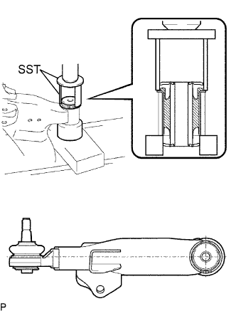
Using SST and a press, press in a new bush.
- SST
- 09710-20011 ( 09710-06071 )
- 09710-22021 ( 09710-01071 )
-
-
INSTALL FRONT LOWER BALL JOINT ATTACHMENT LH
-
Install the ball joint attachment with the nut and a new cotter pin.
- Torque:
- 140 N*m { 1428 kgf*cm, 103 ft.*lbf }
-
-
TEMPORARILY INSTALL FRONT LOWER SUSPENSION ARM SUB-ASSEMBLY LH
-
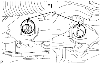
Temporarily install the lower arm, and No. 1 and No. 2 camber adjusting cams with the 2 camber adjusting cams and 2 nuts.
Text in Illustration *1 Matchmark -
Align the matchmarks on the No. 1 camber adjusting cam and No. 2 camber adjusting cam with the corresponding matchmarks on the vehicle frame.
-
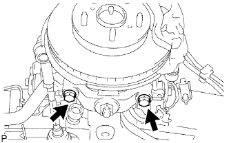
Install the ball joint attachment with the 2 bolts.
- Torque:
- 160 N*m { 1632 kgf*cm, 118 ft.*lbf }
-
-
INSTALL FRONT SPRING BUMPER
-
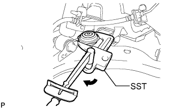
Using SST, install the front spring bumper to the lower arm.
- SST
- 09922-10010
- Torque:
- for use without SST
- 31 N*m { 316 kgf*cm, 23 ft.*lbf }
- for use with SST
- 23 N*m { 231 kgf*cm, 17 ft.*lbf }
Tech Tips
-
Rotate SST in the direction shown in the illustration.
-
Use a torque wrench with a fulcrum length of 345 mm (13.6 in.).
-
-
TEMPORARILY INSTALL FRONT SHOCK ABSORBER WITH COIL SPRING
-
Temporarily install the shock absorber with coil spring with the bolt and nut.
-
-
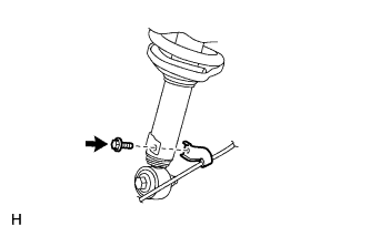
CONNECT FRONT STABILIZER LINK ASSEMBLY LH
-
Connect the stabilizer link to the lower arm with the nut.
- Torque:
- 78 N*m { 795 kgf*cm, 58 ft.*lbf }
Tech Tips
If the ball joint turns together with the nut, use a 6 mm hexagon wrench to hold the stud in place.
-
-
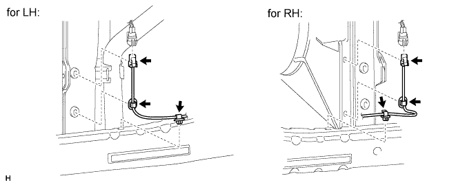
CONNECT FRONT SPEED SENSOR LH (w/ ABS)
-
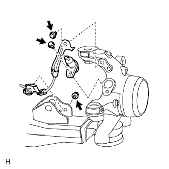
Install the 2 harness clamps with the 2 bolts.
- Torque:
- 32 N*m { 326 kgf*cm, 24 ft.*lbf }
Note
-
When installing the clamp, do not twist the wire harness.
-
Make sure the clamp rotation stopper touches the installation position.
-
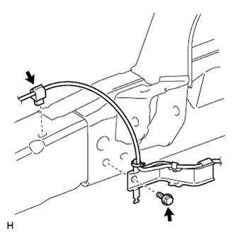
Install the speed sensor with the bolt.
- Torque:
- 8.5 N*m { 87 kgf*cm, 75 in.*lbf }
Note
-
Make sure there are no pieces of iron or other foreign matter attached to the sensor tip.
-
While inserting the speed sensor into the knuckle hole, do not strike or damage the sensor tip.
-
After installing the speed sensor, make sure there is no clearance or foreign matter between the sensor stay part and the knuckle.
-
When installing the sensor, do not twist the wire harness.
-
Install the harness clamp with the bolt.
- Torque:
- 32 N*m { 326 kgf*cm, 24 ft.*lbf }
Note
-
When installing the clamp, do not twist the wire harness.
-
Make sure the clamp rotation stopper touches the installation position.
-
Install the harness clamp with the bolt.
- Torque:
- 32 N*m { 326 kgf*cm, 24 ft.*lbf }
Note
-
When installing the clamp, do not twist the wire harness.
-
Make sure the clamp rotation stopper touches the installation position.
-
Attach the clamp.
-
Connect the connector.
Note
-
Do not attach the connector to the radiator fan shroud before connecting the connector.
-
Securely connect the connector.
-
-
Attach the 2 clamps and the connector.
Note
When attaching the clamps, do not twist the wire harness.
-
-
INSTALL FRONT WHEEL
- Torque:
- 152 N*m { 1,550 kgf*cm, 112 ft.*lbf, for steel type }
- 121 N*m { 1,234 kgf*cm, 89 ft.*lbf, for aluminum type }
-
STABILIZE SUSPENSION
-
Lower the vehicle.
-
Press down on the vehicle several times to stabilize the suspension.
-
-
TIGHTEN FRONT LOWER SUSPENSION ARM SUB-ASSEMBLY LH
-
Tighten the 2 nuts.
- Torque:
- 210 N*m { 2141 kgf*cm, 155 ft.*lbf }
-
-
TIGHTEN FRONT SHOCK ABSORBER WITH COIL SPRING
-
Fix the nut in place and tighten the bolt.
- Torque:
- 95 N*m { 969 kgf*cm, 70 ft.*lbf }
Note
Do not tighten the nut.
-
-
INSPECT AND ADJUST FRONT WHEEL ALIGNMENT