FIT STANDARD / ADJUSTMENT METHOD ADJUSTMENT
-
INSPECT HOOD SUB-ASSEMBLY
-
Check that the clearance measurements of areas *a through *e are within each standard range.
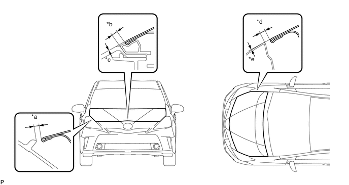
Standard Clearance Area Measurement Area Measurement *a 1.8 to 5.8 mm (0.0709 to 0.228 in.) *b 2.0 to 6.0 mm (0.0787 to 0.236 in.) *c -2.0 to 2.0 mm (-0.0787 to 0.0787 in.) *d 2.5 to 5.5 mm (0.0984 to 0.217 in.) *e -1.5 to 1.5 mm (-0.0591 to 0.0591in.) - - Tech Tips
Centering bolts are used to mount the hood hinge and hood lock. The hood and hood lock cannot be adjusted with the centering bolts installed. Substitute the centering bolts with standard bolts when making adjustments.
-
-
ADJUST HOOD SUB-ASSEMBLY
-
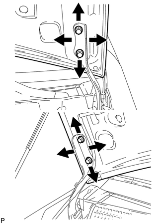
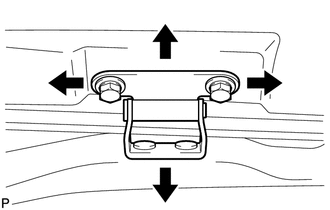
Horizontally and vertically adjust the hood.
-
Loosen the 4 hinge bolts of the hood.
-
Adjust the clearance between the hood and front fender by moving the hood.
-
Tighten the 4 hinge bolts after the adjustment.
- Torque:
- 13 N*m { 133 kgf*cm, 10 ft.*lbf }
-
-
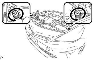
Adjust the height of the front end of the hood using the cushion rubbers.
-
Adjust the 2 cushion rubbers so that the heights of the hood and fender are aligned.
Tech Tips
Raise or lower the front end of the hood by turning the 2 cushion rubbers.
-
-
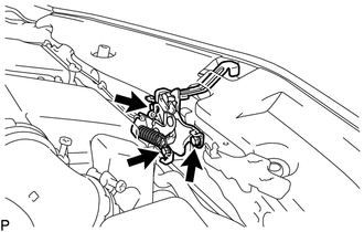
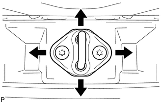
Adjust the hood lock.
-
Loosen the 3 bolts.
-
Tighten the bolts after the adjustment.
- Torque:
- 7.5 N*m { 76 kgf*cm, 66 in.*lbf }
-
Check that the striker can engage with the hood lock smoothly.
-
-
-
INSPECT FRONT DOOR
-
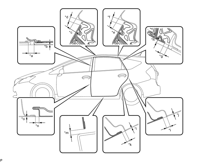
Check that the clearance measurements of areas *a through *m are within each standard range.
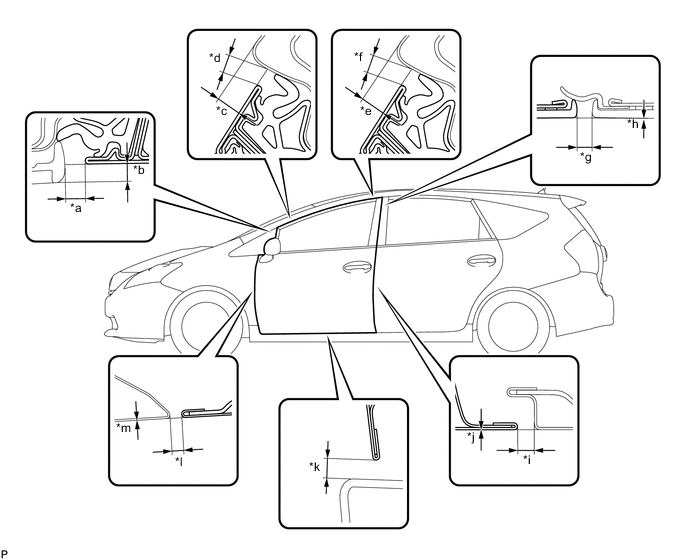
Standard Clearance Area Measurement Area Measurement *a 3.62 to 7.62 mm (0.143 to 0.300 in.) *b 2.92 to 6.92 mm (0.115 to 0.272 in.) *c 5.37 to 8.37 mm (0.211 to 0.330 in.) *d 3.57 to 6.57 mm (0.141 to 0.259 in.) *e 5.37 to 8.37 mm (0.211 to 0.330 in.) *f 3.57 to 6.57 mm (0.141 to 0.259 in.) *g 2.5 to 6.5 mm (0.0984 to 0.256 in.) *h -2.0 to 2.0 mm (-0.0787 to 0.0787 in.) *i 3.0 to 6.0 mm (0.118 to 0.236 in.) *j -1.5 to 1.5 mm (-0.0591 to 0.0591 in.) *k 3.8 to 7.8 mm (0.150 to 0.307 in.) *l 2.5 to 5.5 mm (0.0984 to 0.217 in.) *m -1.5 to 1.5 mm (-0.0591 to 0.0591 in.) - - Tech Tips
-
Use the same procedure for the RH side and LH side.
-
The following procedure is for the LH side.
-
Centering bolts are used to mount the door hinge to the vehicle body and door. The door cannot be adjusted with the centering bolts installed on it. Substitute the centering bolts with standard bolts when making adjustments.
-
-
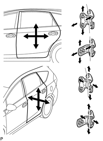
ADJUST FRONT DOOR
Note
Make sure to turn the power switch off when adjusting door lock strikers.
-
Remove the front wheel.
-
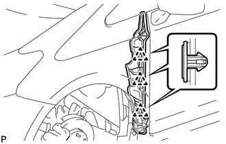
Remove the 3 clips and front fender side panel protector.
-
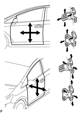
Using SST, loosen the hinge bolts on the vehicle body and adjust the door position.
- SST
- 09812-00010
-
Tighten the hinge bolts on the vehicle body after the adjustment.
- Torque:
- 26 N*m { 265 kgf*cm, 19 ft.*lbf }
-
Loosen the hinge bolts on the door and adjust the door position.
-
Tighten the hinge bolts on the door after the adjustment.
- Torque:
- 26 N*m { 265 kgf*cm, 19 ft.*lbf }
-
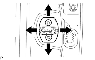
Using a T40 "TORX" socket wrench, slightly loosen the striker mounting screws.
-
Using a brass bar and a hammer, hit the striker to adjust its position.
-
Using a T40 "TORX" socket wrench, tighten the striker mounting screws after the adjustment.
- Torque:
- 23 N*m { 235 kgf*cm, 17 ft.*lbf }
-
Install the front fender side panel protector with 3 new clips.
-
Install the front wheel.
-
-
INSPECT REAR DOOR
-
Check that the clearance measurements of areas *a through *o are within each standard range.
Standard Clearance Area Measurement Area Measurement *a 2.5 to 6.5 mm (0.0984 to 0.256 in.) *b -2.0 to 2.0 mm (-0.0787 to 0.0787 in.) *c 5.57 to 8.57 mm (0.219 to 0.337 in.) *d 3.57 to 6.57 mm (0.141 to 0.259 in.) *e 5.17 to 8.17 mm (0.204 to 0.322 in.) *f 3.57 to 6.57 mm (0.141 to 0.259 in.) *g 4.22 to 8.22 mm (0.166 to 0.324 in.) *h 1.52 to 5.52 mm (0.0598 to 0.217 in.) *i 2.5 to 5.5 mm (0.0984 to 0.217 in.) *j -1.5 to 1.5 mm (-0.0591 to 0.0591 in.) *k 2.5 to 5.5 mm (0.0984 to 0.217 in.) *l -1.5 to 1.5 mm (-0.0591 to 0.0591 in.) *m 3.8 to 7.8 mm (0.150 to 0.307 in.) *n 3.0 to 6.0 mm (0.118 to 0.236 in.) *o -1.5 to 1.5 mm (-0.0591 to 0.0591 in.) - - Tech Tips
-
Use the same procedure for the RH side and LH side.
-
The following procedure is for the LH side.
-
Centering bolts are used to mount the door hinge to the vehicle body and door. The door cannot be adjusted with the centering bolts installed. Substitute the centering bolts with standard bolts when making adjustments.
-
-
ADJUST REAR DOOR
Note
Make sure to turn the power switch off when adjusting door lock strikers.
-
Using SST, loosen the hinge bolts on the vehicle body and adjust the door position.
- SST
- 09812-00010
-
Tighten the hinge bolts on the vehicle body after the adjustment.
- Torque:
- 26 N*m { 265 kgf*cm, 19 ft.*lbf }
-
Loosen the hinge bolts on the door and adjust the door position.
-
Tighten the hinge bolts on the door after the adjustment.
- Torque:
- 26 N*m { 265 kgf*cm, 19 ft.*lbf }
-
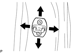
Using a T40 "TORX" socket wrench, slightly loosen the striker mounting screws.
-
Using a brass bar and a hammer, hit the striker to adjust its position.
-
Using a T40 "TORX" socket wrench, tighten the striker mounting screws after the adjustment.
- Torque:
- 23 N*m { 235 kgf*cm, 17 ft.*lbf }
-
-
INSPECT BACK DOOR
-
Check that the clearance measurements of areas *a through *j are within each standard range.
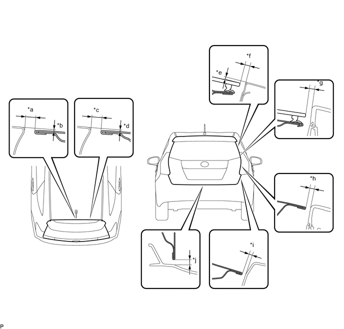
Standard Clearance Area Measurement Area Measurement *a 6.2 to 9.2 mm (0.244 to 0.362 in.) *b -0.1 to 2.9 mm (-0.00394 to 0.114 in.) *c 6.2 to 9.2 mm (0.244 to 0.362 in.) *d -0.1 to 2.9 mm (-0.00394 to 0.114 in.) *e 0.05 to 4.05 mm (0.00197 to 0.159 in.) *f 2.85 to 6.85 mm (0.112 to 0.270 in.) *g 3.0 to 7.0 mm (0.118 to 0.276 in.) *h 3.0 to 7.0 mm (0.118 to 0.276 in.) *i 4.0 to 8.0 mm (0.157 to 0.315 in.) *j 4.0 to 8.0 mm (0.157 to 0.315 in.) Tech Tips
-
Use the same procedure for the RH side and LH side.
-
The following procedure is for the LH side.
-
Centering bolts are used to mount the door hinge to the vehicle body and door. The door cannot be adjusted with the centering bolts installed. Substitute the centering bolts with standard bolts (with washers) when making adjustments.
-
-
ADJUST BACK DOOR
-
Before adjusting the upper end of the back door up and down or left and right, loosen the bolts.
-
Tighten the body side hinge after the adjustment.
- Torque:
- 19 N*m { 194 kgf*cm, 14 ft.*lbf }
-
Using a T40 "TORX" socket wrench, slightly loosen the striker mounting screws.
-
Using a brass bar and a hammer, hit the striker to adjust its position.
-
Using a T40 "TORX" socket wrench, tighten the striker mounting screws after adjustment.
- Torque:
- 23 N*m { 235 kgf*cm, 17 ft.*lbf }
-