FRONT AXLE HUB INSTALLATION
CAUTION / NOTICE / HINT
Use the same procedure for the RH side and LH side.
The following procedure is for the LH side.
PROCEDURE
INSTALL FRONT AXLE HUB BEARING
-
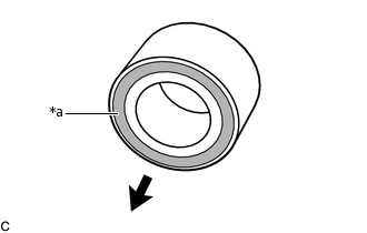
*a
Magnetic Rotor (black)

Inside of the Vehicle
Temporarily install a new front axle hub bearing to the steering knuckle.
Note:Make sure to install the front axle hub bearing so that the magnetic rotor (black) is facing the inside of the vehicle.
-
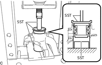
Using SST and a press, install the front axle hub bearing to the steering knuckle.
09608-10010
09649-17010
09950-70010
09951-07100
-
INSTALL FRONT AXLE HUB HOLE SNAP RING
Using snap ring pliers, install a new front axle hub hole snap ring.
Note:After installing the snap ring, check to ensure that it fits securely in place.
INSTALL FRONT STEERING KNUCKLE HEAT INSULATOR
Using a T30 "TORX" socket wrench, install the front steering knuckle heat insulator to the steering knuckle with the bolt.
8.0 N*m
82 kgf*cm
71 in.*lbf
INSTALL FRONT AXLE HUB SUB-ASSEMBLY
-
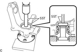
Using SST and a press, install the front axle hub sub-assembly to the steering knuckle.
09950-60010
09951-00630
09950-70010
09951-07100
Note:Do not damage the magnetic seal of the front axle hub bearing.
While installing the front axle hub bearing, confirm that it is able to rotate.
-
INSTALL SKID CONTROL SENSOR COVER
Using a T30 "TORX" socket wrench, install the skid control sensor cover to the steering knuckle with the bolt.
8.0 N*m
82 kgf*cm
71 in.*lbf
INSTALL FRONT AXLE ASSEMBLY
-
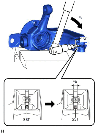
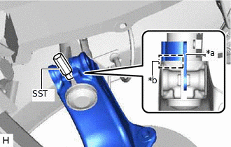
*a
Turn 90°
*b
Maximum 10 mm (0.394 in.)
Secure the front axle assembly in a vise using aluminum plates.
Note:Do not overtighten the vise.
Using SST, widen the steering knuckle slit.
09723-70010
Note:Do not widen the steering knuckle slit to more than 10 mm (0.394 in.).
Do not damage the steering knuckle slit.
Tip:When turning SST, use a 10 mm socket wrench.
-
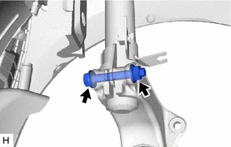
*a
Bracket
*b
Contact
Temporarily install the front axle assembly to the front shock absorber assembly.
Note:Align the bracket of the front shock absorber assembly with the slit of the steering knuckle and install it.
Make sure that the front shock absorber assembly bracket edge comes into contact with the steering knuckle tip.
Do not deform the bracket of the front shock absorber assembly.
Remove SST.
Tip:Turn SST 90° to remove it.
-
Install the bolt and nut.
46 N*m
469 kgf*cm
34 ft.*lbf
Note:Install the nut to the front side of the vehicle.
When installing the nut, keep the bolt from rotating.
Remove any foreign matter such as iron particles on the magnetic seal.
-
CONNECT FRONT DRIVE SHAFT ASSEMBLY
-
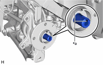
*a
Matchmark
Align the matchmarks on the front drive shaft assembly and front axle hub sub-assembly, and connect the front drive shaft assembly to the front axle hub sub-assembly.
Note:Do not push the front axle assembly further out of the vehicle than is necessary.
Do not damage the front drive shaft outboard joint boot.
Do not damage the magnetic seal of the front axle hub bearing.
Check that there is no foreign matter on the front axle hub bearing and contact surfaces of the front drive shaft assembly.
-
CONNECT FRONT LOWER NO. 1 SUSPENSION ARM SUB-ASSEMBLY
INSTALL FRONT STABILIZER BAR
-
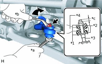
*1
No. 1 Cushion Retainer
*2
Front Stabilizer Cushion
*3
Front Stabilizer Bolt
*4
Front Stabilizer Bar
*a
Hold
*b
Turn
*c
4.0 mm (0.157 in.) or more
Temporarily install the 2 No. 1 cushion retainers, 2 front stabilizer cushions and front stabilizer bar with a new nut as shown in the illustration.
Note:Make sure to install the front stabilizer bar so that the protrusion of the front stabilizer cushion is inserted into the hole of the front stabilizer bar.
Using a wrench to hold the front stabilizer bolt, tighten the nut.
18 N*m
184 kgf*cm
13 ft.*lbf
-
CONNECT TIE ROD END SUB-ASSEMBLY
INSTALL FRONT DISC
INSTALL FRONT DISC BRAKE CALIPER ASSEMBLY
TEMPORARILY INSTALL FRONT AXLE SHAFT NUT
Clean the threaded parts on the front drive shaft assembly and a new front axle shaft nut using non-residue solvent.
Note:Be sure to perform this work even when using a new drive shaft.
Keep the threaded parts free of oil and foreign matter.
Using a 30 mm socket wrench, while applying the brakes, temporarily install the front axle shaft nut.
216 N*m
2203 kgf*cm
159 ft.*lbf
Note:Stake the front axle shaft nut after inspecting for looseness and runout in the following steps.
Tip:Keep depressing the brake pedal to prevent the drive shaft from rotating.
SEPARATE FRONT DISC BRAKE CALIPER ASSEMBLY
REMOVE FRONT DISC
INSPECT FRONT AXLE HUB BEARING LOOSENESS
INSPECT FRONT AXLE HUB RUNOUT
INSTALL FRONT DISC
INSTALL FRONT DISC BRAKE CALIPER ASSEMBLY
INSTALL FRONT SPEED SENSOR
-
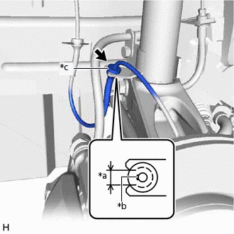
*a
Notch
*b
Paint Line
*c
Grommet
Connect the front speed sensor to the front shock absorber assembly bracket.
Note:Install the grommet with the paint line of the front speed sensor wire placed between the notch of the front shock absorber assembly bracket.
Do not twist the front speed sensor wire harness when installing it.
Install the front speed sensor to the steering knuckle with the bolt.
8.0 N*m
82 kgf*cm
71 in.*lbf
Note:Prevent foreign matter from attaching to the front speed sensor tip.
Firmly insert the front speed sensor body into the steering knuckle before tightening the bolt.
After installing the front speed sensor to the steering knuckle, make sure that there is no clearance between the front speed sensor stay and steering knuckle. Also make sure that no foreign matter is stuck between the parts.
Do not twist the front speed sensor wire harness when installing it.
-
STAKE FRONT AXLE SHAFT NUT
-
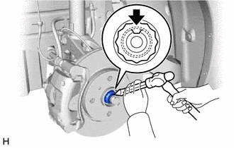
Using a chisel and hammer, stake the front axle shaft nut.
-
FULLY TIGHTEN HEXALOBULAR SCREW
INSTALL FRONT WHEEL
INSPECT AND ADJUST FRONT WHEEL ALIGNMENT
CHECK FOR SPEED SENSOR SIGNAL