FUEL FILTER REPLACEMENT
CAUTION / NOTICE / HINT
When working on the fuel circuit, protect the generator assembly against contamination. Cover the generator assembly with suitable materials. Failure to comply with this procedure may result in a generator assembly malfunction.
PROCEDURE
REMOVE AIR CLEANER CAP SUB-ASSEMBLY WITH AIR CLEANER HOSE ASSEMBLY
REMOVE AIR CLEANER FILTER ELEMENT SUB-ASSEMBLY
REMOVE AIR CLEANER CASE SUB-ASSEMBLY
REMOVE NO. 1 FUEL FILTER PROTECTOR (w/ Fuel Heater Relay)
-
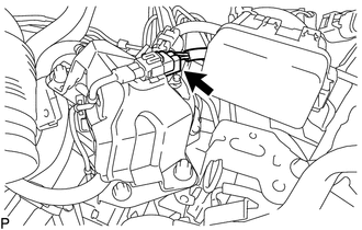
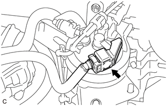
Disconnect the level warning switch connector.
-
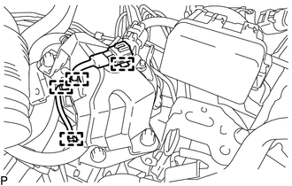
Disengage the 4 clamps to disconnect the level warning switch connector from the No. 1 fuel filter protector.
-
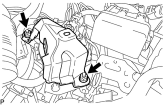
Remove the 2 nuts and No. 1 fuel filter protector.
-
REMOVE NO. 1 FUEL FILTER PROTECTOR (w/o Fuel Heater Relay)
-
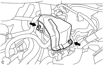
Remove the 2 nuts and No. 1 fuel filter protector.
-
REMOVE FUEL FILTER ASSEMBLY (w/ Fuel Heater Relay)
-
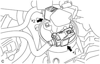
Remove the No. 2 fuel pipe clamp from the No. 1 fuel hose.
-
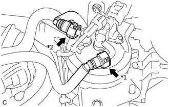
*1
No. 1 Fuel Hose
*2
No. 3 Fuel Hose
Disconnect the No. 1 fuel hose and No. 3 fuel hose from the fuel filter assembly.
-
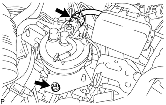
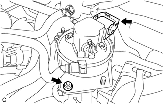
Disconnect the fuel filter assembly connector.
Remove the nut and fuel filter assembly from the fuel filter support.
-
Remove the bolt and fuel filter cover from the fuel filter assembly.
-
REMOVE FUEL FILTER ASSEMBLY (w/o Fuel Heater Relay)
-
*1
No. 2 Fuel Pipe Clamp
*2
No. 3 Fuel Pipe Clamp
Remove the No. 2 fuel pipe clamp and No. 3 fuel pipe clamp from the No. 1 fuel hose and No. 3 fuel hose.
-
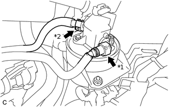
*1
No. 1 Fuel Hose
*2
No. 3 Fuel Hose
Disconnect the No. 1 fuel hose and No. 3 fuel hose from the fuel filter assembly.
-
Disconnect the fuel filter assembly connector.
Remove the nut and fuel filter assembly from the fuel filter support.
-
Remove the bolt and fuel filter cover from the fuel filter assembly.
-
DRAIN FUEL (w/ Fuel Heater Relay)
-
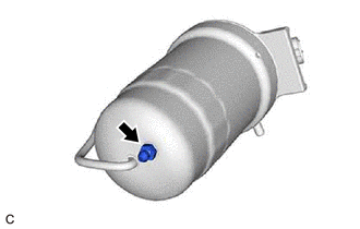
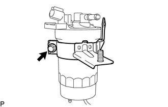
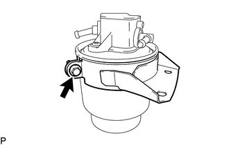
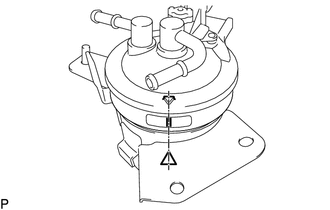
Loosen the drain cock and drain the fuel from the fuel filter assembly.
-
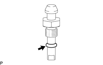
Remove the O-ring from the drain cock.
Tighten the drain cock.
3.1 N*m
32 kgf*cm
27 in.*lbf
-
DRAIN FUEL (w/o Fuel Heater Relay)
Loosen the drain cock and drain the fuel from the fuel filter assembly.
REMOVE FUEL FILTER ELEMENT ASSEMBLY (w/ Fuel Heater Relay)
-
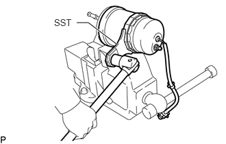
Secure the fuel filter assembly in a vice between aluminum plates.
Using SST, remove the fuel filter case from the fuel filter cap.
09228-64010
Note:Be careful not to damage the fuel filter cap.
Remove the fuel filter cap from the vice.
-
Remove the O-ring from the fuel filter cap.
Remove the fuel filter element assembly from the fuel filter case.
-
INSTALL FUEL FILTER ELEMENT ASSEMBLY (w/ Fuel Heater Relay)
Check and clean the installation surface of the fuel filter case and fuel filter cap.
Apply fuel to the O-ring of a new fuel filter cap.
Install a new fuel filter element assembly to the fuel filter case.
-
Secure the fuel filter cap in the vice between aluminum plates.
Using SST, install the fuel filter case to the fuel filter cap.
09228-64010
-
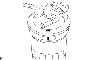
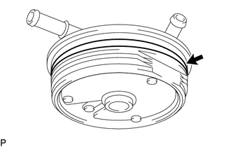
Align the mark on the fuel filter cap and fuel filter case.
Remove the fuel filter assembly from the vice.
INSTALL FUEL FILTER ASSEMBLY (w/ Fuel Heater Relay)
-
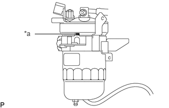
*a
Protrusion
Press the protrusion of the fuel filter cover against the fuel filter case.
-
Align the mark on the fuel filter cap, fuel filter cover and the fuel filter case.
Install the fuel filter cover to the fuel filter assembly with the bolt.
12.5 N*m
127 kgf*cm
111 in.*lbf
Install the fuel filter assembly to the fuel filter support with the nut.
17.5 N*m
178 kgf*cm
13 ft.*lbf
Connect the fuel filter assembly connector.
Connect the No. 1 fuel hose and No. 3 fuel hose to the fuel filter assembly.
Install the No. 2 fuel pipe clamp to the No. 1 fuel hose.
-
INSTALL FUEL FILTER ASSEMBLY (w/o Fuel Heater Relay)
Install the fuel filter cover to a new fuel filter assembly with the bolt.
7.0 N*m
71 kgf*cm
62 in.*lbf
Install the fuel filter assembly to the fuel filter support with the nut.
17.5 N*m
178 kgf*cm
13 ft.*lbf
Connect the fuel filter assembly connector.
Connect the No. 1 fuel hose and No. 3 fuel hose to the fuel filter assembly.
Install the No. 2 fuel pipe clamp and No. 3 fuel pipe clamp to the No. 1 fuel hose and No. 3 fuel hose.
INSTALL NO. 1 FUEL FILTER PROTECTOR (w/ Fuel Heater Relay)
Install the No. 1 fuel filter protector with the 2 nuts.
17.5 N*m
178 kgf*cm
13 ft.*lbf
Engage the 4 clamps to connect the level warning switch connector to the No. 1 fuel filter protector.
Connect the level warning switch connector.
INSTALL NO. 1 FUEL FILTER PROTECTOR (w/o Fuel Heater Relay)
Install the No. 1 fuel filter protector with the 2 nuts.
17.5 N*m
178 kgf*cm
13 ft.*lbf
INSTALL AIR CLEANER CASE SUB-ASSEMBLY
INSTALL AIR CLEANER FILTER ELEMENT SUB-ASSEMBLY
INSTALL AIR CLEANER CAP SUB-ASSEMBLY WITH AIR CLEANER HOSE ASSEMBLY
INSPECT FOR FUEL LEAK