CYLINDER BLOCK DISASSEMBLY
PROCEDURE
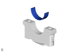
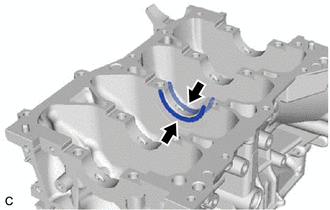
REMOVE CYLINDER BLOCK WATER JACKET SPACER
-
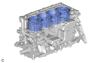
Remove the cylinder block water jacket spacer from the cylinder block sub-assembly.
-
REMOVE NO. 1 VENTILATION CASE
Tip:There are 2 installation types for the No. 1 ventilation case.
Depending on the installation type, the number of bolts, nuts and stud bolts used will vary.
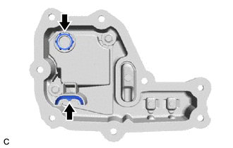
Type A:
-
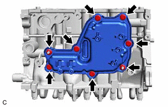
Remove the 6 bolts and 2 nuts.
-
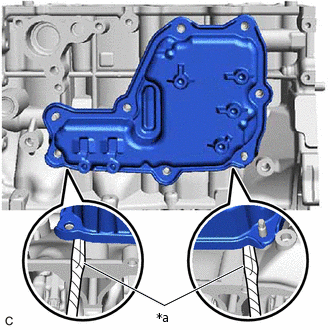
*a
Protective Tape
Remove the No. 1 ventilation case by prying between the No. 1 ventilation case and cylinder block sub-assembly with a screwdriver with its tip wrapped with protective tape.
Note:Be careful not to damage the contact surfaces of the cylinder block sub-assembly and No. 1 ventilation case.
-
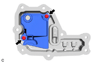
Type B:
-
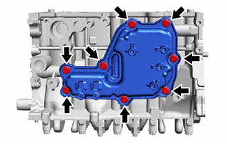
Remove the 8 bolts.
-
*a
Protective Tape
Remove the No. 1 ventilation case by prying between the No. 1 ventilation case and cylinder block sub-assembly with a screwdriver with its tip wrapped with protective tape.
Note:Be careful not to damage the contact surfaces of the cylinder block sub-assembly and No. 1 ventilation case.
-
-
Remove the 2 oil separator gaskets from the case separator.
-
Remove the 2 bolts and case separator from the No. 1 ventilation case.
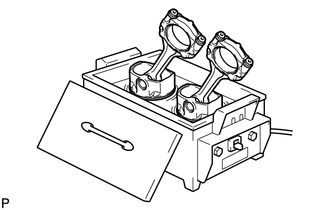
REMOVE PISTON SUB-ASSEMBLY WITH CONNECTING ROD
-
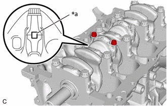
*a
Paint Mark
Place a paint mark across each corresponding connecting rod and connecting rod bearing cap.
Tip:The paint marks are used to ensure that the same parts are installed in the same combination to their original locations.
-
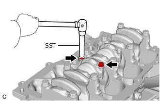
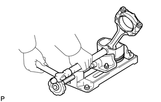
Using SST, remove the 8 connecting rod bolts from the connecting rod bearing caps.
09205-16011
-
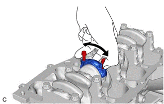
Using the 2 removed connecting rod bolts, remove the 4 connecting rod bearing caps with lower connecting rod bearings by wiggling each connecting rod cap back and forth.
Tip:Keep the lower connecting rod bearing installed to the connecting rod cap.
Push out the 4 piston sub-assembly with pins with connecting rods and connecting rod bearings through the top of the cylinder block sub-assembly.
Tip:Keep the connecting rod bearing, connecting rod and connecting rod bearing cap together.
Arrange the removed parts in such a way that they can be reinstalled to their original locations.
-
REMOVE CONNECTING ROD BEARING
Remove the 8 connecting rod bearings from the 4 connecting rods and 4 connecting rod bearing caps.
Tip:Arrange the removed parts in such a way that they can be reinstalled to their original locations.
REMOVE CRANKSHAFT
-
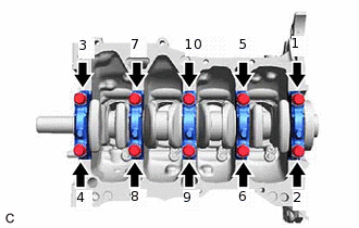
Uniformly loosen and remove the 10 crankshaft bearing cap set bolts in several steps in the order shown in the illustration.
-
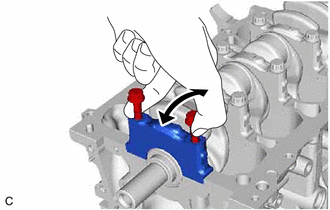
Using the 2 removed crankshaft bearing cap set bolts, remove the 5 No. 1 crankshaft bearing caps from the cylinder block sub-assembly by wigging each crankshaft bearing cap back and forth.
Tip:Arrange the removed parts in such a way that they can be reinstalled to their original locations.
Remove the crankshaft from the cylinder block sub-assembly.
-
REMOVE CRANKSHAFT BEARING
-
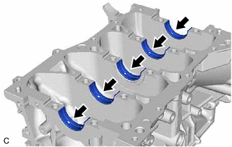
Remove the 5 upper crankshaft bearings from the cylinder block sub-assembly.
Tip:Arrange the removed parts in such a way that they can be reinstalled to their original locations.
-
Remove the 5 lower crankshaft bearings from the 5 No. 1 crankshaft bearing caps.
Tip:Arrange the removed parts in such a way that they can be reinstalled to their original locations.
-
REMOVE UPPER CRANKSHAFT THRUST WASHER
-
Remove the 2 upper crankshaft thrust washers from the cylinder block sub-assembly.
-
REMOVE PISTON RING SET
-
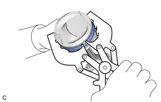
Using a piston ring expander, remove the No. 1 compression ring and No. 2 compression ring from the piston.
Remove the oil ring expander, upper side rail and lower side rail from the piston by hand.
Tip:Arrange the removed parts in such a way that they can be reinstalled to their original locations.
-
REMOVE PISTON SUB-ASSEMBLY WITH PIN
-
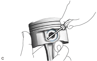
Using a screwdriver, pry out the piston pin hole snap ring from the piston.
Note:Do not remove the piston pin hole snap ring (rear side) unless it is being replaced.
Be careful not to damage the piston when removing the piston pin hole snap ring (rear side).
-
Gradually heat the piston to approximately 80°C (176°F).
CAUTION:Be sure to wear protective gloves.
-
Using a brass bar and a hammer, lightly tap out the piston pin and remove the connecting rod.
Tip:The piston and piston pin are a matched set.
Arrange the removed parts in such a way that they can be reinstalled to their original locations.
-
REMOVE NO. 1 OIL NOZZLE SUB-ASSEMBLY
-
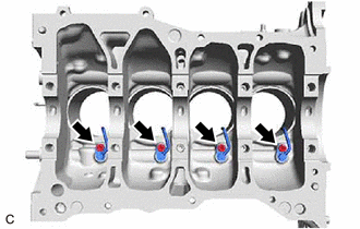
Using a 5 mm hexagon socket wrench, remove the 4 bolts and 4 No. 1 oil nozzle sub-assemblies from the cylinder block sub-assembly.
-
REMOVE OIL JET
-
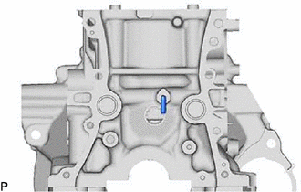
Remove the oil jet from the cylinder block sub-assembly.
-