WATER PUMP (w/o EGR Cooler) REMOVAL
Note
-
When replacing the injectors (including shuffling the injectors between the cylinders), common rail or cylinder head, it is necessary to replace the injection pipes with new ones.
-
When replacing the fuel supply pump, common rail, cylinder block, cylinder head, cylinder head gasket or timing gear case, it is necessary to replace the fuel inlet pipe with a new one.
-
After removing the injection pipes, clean them with a brush and compressed air.
-
PRECAUTION
Note
After turning the ignition switch off, waiting time may be required before disconnecting the cable from the battery terminal. Therefore, make sure to read the disconnecting the cable from the battery terminal notice before proceeding with work Click here.
-
DISCONNECT CABLE FROM NEGATIVE BATTERY TERMINAL
Note
When disconnecting the cable, some systems need to be initialized after the cable is reconnected Click here.
-
REMOVE NO. 1 ENGINE UNDER COVER (for 4WD and Pre-Runner)
-
DRAIN ENGINE COOLANT
Note
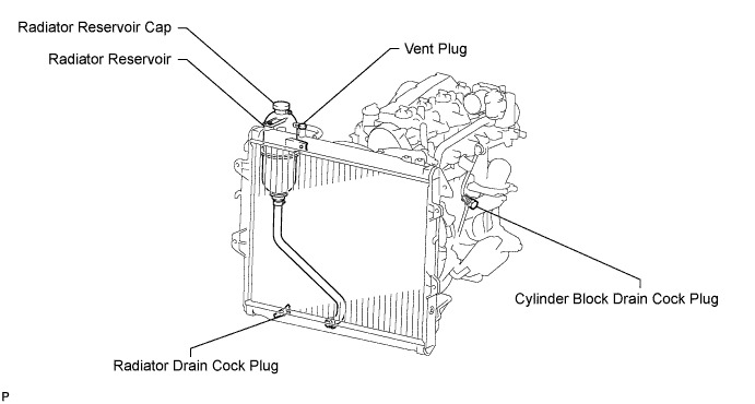
Do not remove the radiator reservoir cap while the engine and radiator are still hot. Pressurized, hot engine coolant and steam may be released and cause serious burns.
-

Drain the coolant by removing the reservoir cap and, using a wrench, remove the vent plug.
-
Loosen the cylinder block drain cock plug and the radiator drain cock plug.
Tech Tips
Collect the coolant in a container and dispose of it according to the regulations in your area.
-
-
REMOVE INTERCOOLER ASSEMBLY (w/ Intercooler)
-
REMOVE NO. 2 AIR CLEANER PIPE SUB-ASSEMBLY (w/o Intercooler)
-
w/ No. 1 Engine Cover
-
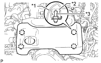
Text in Illustration *1 No. 1 Engine Cover Sub-assembly *2 Claw *3 Pin Detach the 4 claws from the pins of the engine cover bracket and remove the No. 1 engine cover sub-assembly.
-
Remove the 2 bolts and engine cover bracket.
-
-
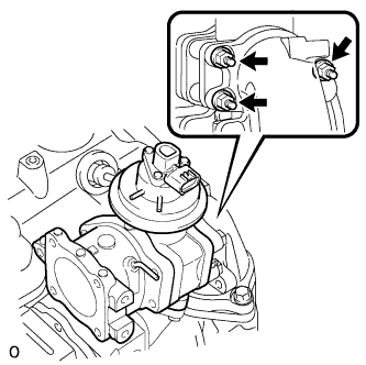
Disconnect the manifold absolute pressure sensor connector.
-
Disconnect the vacuum hose from the gas filter.
-
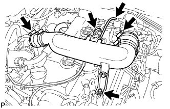
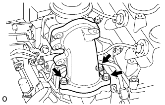
Loosen the 2 clamps.
-
Remove the bolt and disconnect the No. 2 air cleaner pipe sub-assembly together with the 2 air hoses.
-
-
REMOVE RADIATOR HOSE INLET
-
REMOVE FAN SHROUD
-
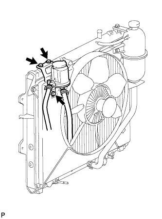
Remove the 3 bolts and oil reservoir.
-
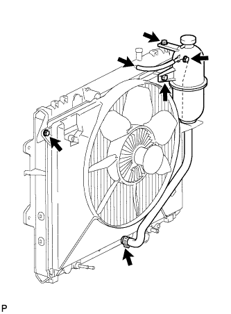
Disconnect the No. 1 and No. 2 water by-pass hoses from the radiator.
-
Remove the 2 bolts and radiator reservoir.
-
Loosen the 4 nuts holding the fluid coupling with fan.
-
Remove the fan and generator V belt Click here.
-
Remove the 2 bolts holding the fan shroud.
-
Remove the 4 nuts of the fluid coupling with fan, and then remove the fan shroud together with the fluid coupling with fan.
Note
Be careful not to damage the radiator core.
-
Remove the fan pulley from the engine water pump.
-
-
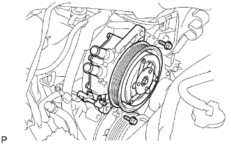
DISCONNECT COOLER COMPRESSOR ASSEMBLY (w/ Air Conditioning System)
-
Remove the 4 bolts and disconnect the cooler compressor assembly.
Tech Tips
It is not necessary to completely remove the compressor assembly. With the hoses connected to the compressor assembly, hang the compressor assembly on the vehicle body with a rope.
-
-
REMOVE VISCOUS HEATER WITH MAGNET CLUTCH ASSEMBLY (w/ Viscous Heater)
-
Disconnect the connector.
-
Remove the 2 bolts and viscous with magnet clutch heater assembly.
-
-
REMOVE NO. 1 VISCOUS HEATER BRACKET SUB-ASSEMBLY (w/ Viscous Heater)
-
Remove the 4 bolts and No. 1 viscous heater bracket sub-assembly.
-
-
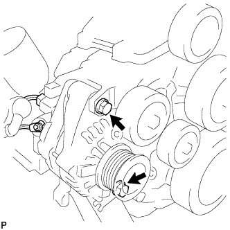
REMOVE GENERATOR ASSEMBLY
-
Remove the nut and generator wire.
-
Disconnect the generator connector.
-
Remove the 2 bolts and generator.
-
-
REMOVE GENERATOR BRACKET
-
Remove the bolt and generator bracket.
-
-
REMOVE V-RIBBED BELT TENSIONER ASSEMBLY
-
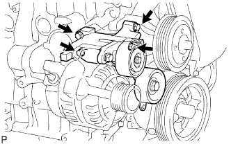
Remove the 4 bolts and V-ribbed belt tensioner assembly.
-
-
REMOVE DIESEL THROTTLE BODY ASSEMBLY (w/ Intercooler)
-
Disconnect the 2 connectors.
-
Remove the 2 bolts, 2 nuts, diesel throttle body assembly and gasket.
-
-
REMOVE NO. 1, NO. 2 AND NO. 3 INJECTION PIPE SUB-ASSEMBLY
Note
-
After removing the fuel pipe, cover the outlets on the common rail with tape to keep out foreign matter.
-
After removing the fuel pipe, put it in a plastic bag to prevent foreign matter from contaminating its injector inlet.
-
w/ Intercooler:
-
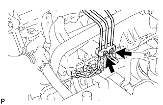
Remove the 2 nuts and No. 3 injection pipe clamp.
-
Remove the 2 bolts and 2 No. 2 injection pipe clamps.
-
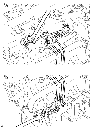
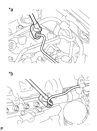
Text in Illustration *a Injector Side *b Common Rail Side Using a 17 mm union nut wrench, loosen the union nuts and remove the No. 1, No. 2 and No. 3 injection pipes.
-
-
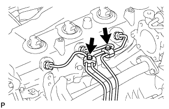
w/o Intercooler:
-
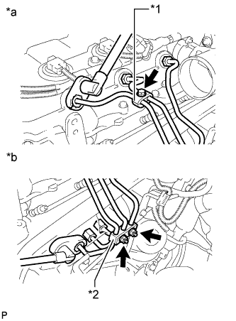
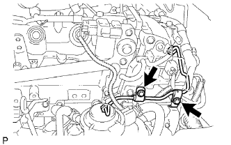
Text in Illustration *1 No. 2 Injection Pipe Clamp *2 No. 3 Injection Pipe Clamp *a Injector Side *b Common Rail Side Remove the bolt and No. 2 injection pipe clamp.
-
Remove the 2 nuts and No. 3 injection pipe clamp.
-
Using a 17 mm union nut wrench, loosen the union nuts and remove the No. 1, No. 2 and No. 3 injection pipes.
-
-
-
REMOVE NO. 2 INTAKE AIR CONNECTOR BRACKET (w/ Intercooler)
-
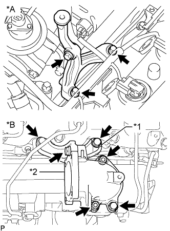
Text in Illustration *A w/ Intercooler *B w/o Intercooler *1 No. 2 Intake Air Connector Bracket *2 Intake Air Connector Remove the 3 bolts and No. 2 intake air connector bracket.
-
-
DISCONNECT NO. 3 WATER BY-PASS PIPE (w/ Intercooler)
-
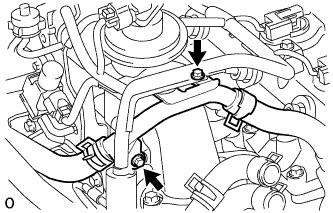
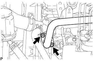
Remove the 2 bolts and disconnect the No. 3 water by-pass pipe with the wire harness.
-
-
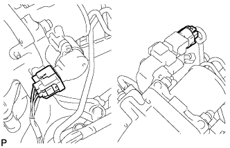
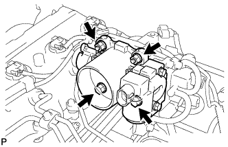
REMOVE ELECTRIC VACUUM REGULATING VALVE ASSEMBLY (w/ Intercooler)
-
w/ Intercooler:
-
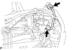
Disconnect the 2 connectors.
-
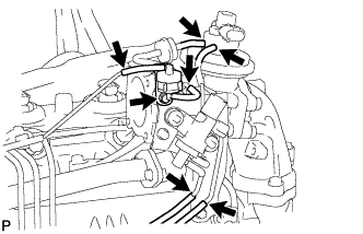
Disconnect the 6 vacuum hoses.
-
Remove the bolt and No. 1 gas filter with gas filter bracket.
-
Remove the 2 bolts and electric vacuum regulating valve.
-
-
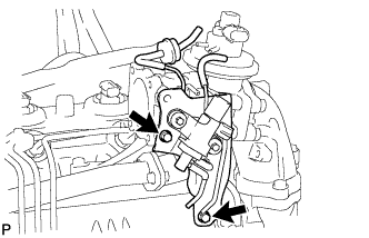
w/o Intercooler:
-
Disconnect the connector.
-
Disconnect the 2 vacuum hoses.
-
Remove the 2 bolts and electric vacuum regulating valve together with the bracket.
Note
Do not remove the electric vacuum regulating valve from the bracket.
-
-
-
REMOVE NO. 2 INTAKE AIR CONNECTOR (w/ Intercooler)
-
Remove the 3 nuts, No. 2 intake air connector and gasket.
-
-
REMOVE INTAKE AIR CONNECTOR (w/ Intercooler)
-
Remove the 3 bolts, intake air connector and 2 gaskets.
-
-
REMOVE ELECTRIC EGR CONTROL VALVE ASSEMBLY WITH NO. 1 EGR PIPE SUB-ASSEMBLY (w/ Intercooler)
-
Remove the 2 nuts, electric EGR control valve with No. 1 EGR pipe and gasket.
-
-
REMOVE NO. 4 INJECTION PIPE SUB-ASSEMBLY
Note
If an injection pipe clamp is removed from the No. 4 injection pipe, replace the injection clamp with a new one.
-
w/ Intercooler:
-
Remove the bolt and disconnect the injection pipe clamp.
-
Text in Illustration *a Injector Side *b Common Rail Side Using a 17 mm union nut wrench, loosen the union nuts and remove the No. 4 injection pipe.
-
-
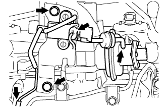
w/o Intercooler:
-
Remove the 2 bolts and disconnect the 2 injection pipe clamps.
-
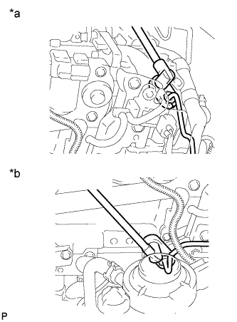
Text in Illustration *a Injector Side *b Common Rail Side Using a 17 mm union nut wrench, loosen the union nuts and remove the No. 4 injection pipe.
-
-
-
REMOVE CYLINDER HEAD COVER SUB-ASSEMBLY
Note
If the cylinder head cover is removed, replace the 4 No. 3 cylinder head cover gaskets with new ones.
-
Remove the 3 bolts and disconnect the 4 injector connectors.
-
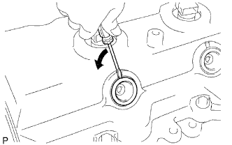
Using a small screwdriver, remove the nozzle holder seal by prying between the nozzle holder seal and the cutout part of the cylinder head cover.
-
Disconnect the ventilation hose.
-
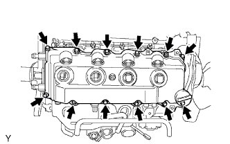
Remove the 10 bolts, 2 nuts, cylinder head cover and cylinder head cover gasket.
-
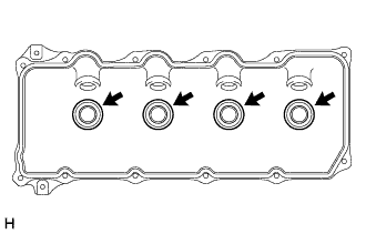
Remove the 4 No. 3 cylinder head cover gaskets from the cylinder head cover.
-
-
REMOVE NO. 1 TIMING BELT COVER
-
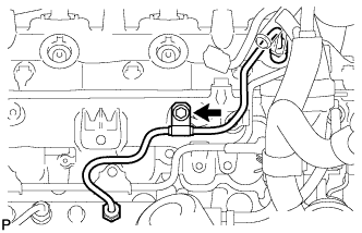
Remove the bolt and water hose clamp.
-
Remove the wire harness clamp.
-
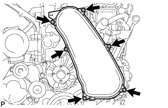
Remove the 6 bolts and timing belt cover.
-
-
REMOVE TIMING BELT
-
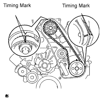
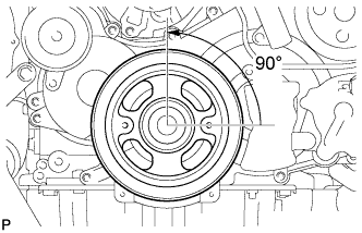
Turn the crankshaft clockwise and align the timing marks as shown in the illustration.
-
Uniformly loosen the 2 bolts and remove the timing belt tensioner.
-
Remove the timing belt.
-
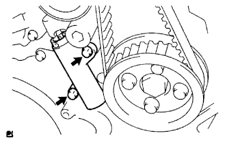
Using a 10 mm hexagon wrench, remove the bolt, timing belt idler and washer.
Tech Tips
-
When turning the camshaft while the timing belt is removed, turn the crankshaft 90° counterclockwise.
-
When installing the timing belt, return the camshaft to the timing marks and then turn the crankshaft clockwise until it aligns with the timing marks, as shown in the illustration.
-
-
-
REMOVE CAMSHAFT TIMING PULLEY
-
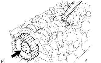
Remove the bolt of the camshaft timing pulley while holding the camshaft with a wrench.
Note
Make sure the timing belt is not installed when removing the bolt of the camshaft timing pulley.
-
Remove the camshaft timing pulley.
-
-
REMOVE NO. 2 TIMING BELT COVER
-
Remove the 4 bolts, nut and No. 2 timing belt cover.
-
-
REMOVE ENGINE WATER PUMP ASSEMBLY
-
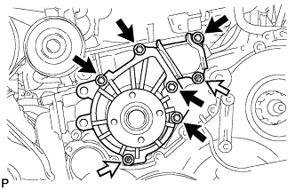
Remove the 5 bolts, 2 nuts, engine water pump and gasket.
Text in Illustration 
Bolt 
Nut
-