SPEED LIMITER SYSTEM TERMINALS OF ECM
CHECK ECM
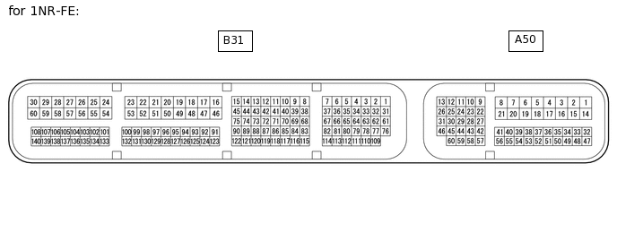
Table 1. for 1NR-FE: Terminal No. (Symbol)
Wiring Color
Terminal Description
Condition
Specified Condition
A50-1 (BATT) - Body ground
P - Body ground
Power source circuit
Always
11 to 14 V
A50-37 (IGSW) - Body ground
B - Body ground
IG power source circuit
Ignition switch ON
11 to 14 V
Ignition switch off
Below 1 V
A50-40 (ASLM) - Body ground
GR - Body ground
Speed limiter switch signal
Speed limiter switch on
Below 1 Ω
Speed limiter switch off
10 kΩ or higher
B31-16 (E1) - Body ground
BR - Body ground
Ground
Always
Below 1 Ω
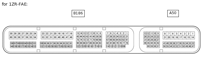
Table 2. for 1ZR-FAE: Terminal No. (Symbol)
Wiring Color
Terminal Description
Condition
Specified Condition
A50-1 (BATT) - Body ground
P - Body ground
Power source circuit
Always
11 to 14 V
A50-6 (IGSW) - Body ground
B - Body ground
IG power source circuit
Ignition switch ON
11 to 14 V
Ignition switch off
Below 1 V
A50-20 (ASLM) - Body ground
GR - Body ground
Speed limiter switch signal
Speed limiter switch on
Below 1 Ω
Speed limiter switch off
10 kΩ or higher
B186-59 (E1) - Body ground
BR - Body ground
Ground
Always
Below 1 Ω

Table 3. for 8NR-FTS: Terminal No. (Symbol)
Wiring Color
Terminal Description
Condition
Specified Condition
A173-1 (BATT) - Body ground
B - Body ground
Power source circuit
Always
11 to 14 V
A173-6 (IGSW) - Body ground
L - Body ground
IG power source circuit
Ignition switch ON
11 to 14 V
Ignition switch off
Below 1 V
A173-22 (ASLM) - A173-41 (ECCS)
GR - Body ground
Speed limiter switch signal
Speed limiter switch on
Below 1 Ω
Speed limiter switch off
10 kΩ or higher
B208-53 (E1) - Body ground
W-B - Body ground
Ground
Always
Below 1 Ω

Table 4. for 1ND-TV: Terminal No. (Symbol)
Wiring Color
Terminal Description
Condition
Specified Condition
A169-15 (BATT) - Body ground
W - Body ground
Power source circuit
Always
11 to 14 V
A169-37 (IGSW) - Body ground
B - Body ground
IG power source circuit
Ignition switch ON
11 to 14 V
Ignition switch off
Below 1 V
A169-39 (ASLM) - A169-59 (ECCS)
GR - Body ground
Speed limiter switch signal
Speed limiter switch on
Below 1 Ω
Speed limiter switch off
10 kΩ or higher
A169-4 (E1) - Body ground
W-B - Body ground
Ground
Always
Below 1 Ω
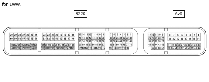
Table 5. for 1WW: Terminal No. (Symbol)
Wiring Color
Terminal Description
Condition
Specified Condition
A50-15 (BATT) - Body ground
B - Body ground
Power source circuit
Always
11 to 14 V
A50-26 (IGSW) - Body ground
B - Body ground
IG power source circuit
Ignition switch ON
11 to 14 V
Ignition switch off
Below 1 V
A50-49 (ASLM) - A50-42 (ECCS)
GR - Body ground
Speed limiter switch signal
Speed limiter switch on
Below 1 Ω
Speed limiter switch off
10 kΩ or higher
A50-4 (E1) - Body ground
W-B - Body ground
Ground
Always
Below 1 Ω