POWER WINDOW CONTROL SYSTEM TERMINALS OF ECU
-
CHECK POWER WINDOW REGULATOR MASTER SWITCH ASSEMBLY (except Double Cab, w/o Jam Protection)
-
*1: for LHD
-
*2: for RHD
-
*3: w/o Regulator
-
*4: w/ Regulator
-
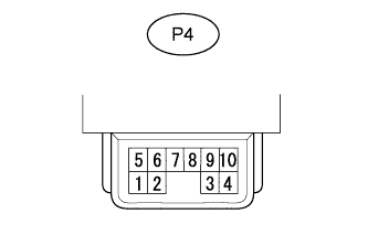
Disconnect the P4 power window regulator master switch assembly connector.
-
Measure the voltage and resistance according to the value(s) in the table below.
Terminal No. (Symbol) Wiring Color Terminal Description Condition Specified Condition P4-9 (B) - Body ground L - Body ground Ignition power supply Ignition switch off Below 1 V P4-9 (B) - Body ground L - Body ground Ignition power supply Ignition switch ON 11 to 14 V P4-1 (E) - Body ground*1
P4-10 (E) - Body ground*2
W-B - Body ground Ground Always Below 1 Ω If the result is not as specified, there may be a malfunction on the wire harness side.
-
Reconnect the P4 power window regulator master switch assembly connector.
-
Measure the voltage according to the value(s) in the table below.
Terminal No. (Symbol) Wiring Color Terminal Description Condition Specified Condition P4-3 (U) - P4-1 (E)*1
P4-2 (U) - P4-10 (E)*2
R - W-B*1
B - W-B*2
-
Front power window regulator motor assembly (for driver side) up output*3
-
Front door window regulator sub-assembly (for driver side) up output*4
Ignition switch ON, driver side power window switch off → up Below 1 V → 11 to 14 V P4-4 (D) - P4-1 (E)*1
P4-5 (D) - P4-10 (E)*2
L-R - W-B
-
Front power window regulator motor assembly (for driver side) down output*3
-
Front door window regulator sub-assembly (for driver side) down output*4
Ignition switch ON, driver side power window switch off → down (manual operation) Below 1 V → 11 to 14 V Ignition switch ON, driver side power window fully closed → driver side power window switch down (auto operation) → driver side power window fully open Below 1 V → 11 to 14 V → Below 1 V P4-8 (U) - P4-1 (E)*1
P4-8 (U) - P4-10 (E)*2
R-L - W-B
-
Front power window regulator motor assembly (for front passenger side) up output*3
-
Front door window regulator sub-assembly (for front passenger side) up output*4
-
Window lock switch off
-
Ignition switch ON, front passenger side power window remote manual switch off → up
Below 1 V → 11 to 14 V P4-10 (D) - P4-1 (E)*1
P4-1 (D) - P4-10 (E)*2
G-W - W-B
-
Front power window regulator motor assembly (for front passenger side) down output*3
-
Front door window regulator sub-assembly (for front passenger side) down output*4
-
Window lock switch off
-
Ignition switch ON, front passenger side power window remote manual switch off → down
Below 1 V → 11 to 14 V If the result is not as specified, the master switch may have a malfunction.
-
-
-
CHECK POWER WINDOW REGULATOR MASTER SWITCH ASSEMBLY (for Double Cab, w/o Jam Protection)
-
*1: for LHD
-
*2: for RHD
-
*3: w/o Regulator
-
*4: w/ Regulator
-
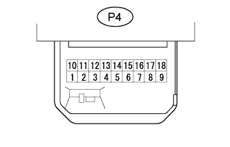
Disconnect the P4 power window regulator master switch assembly connector.
-
Measure the voltage and resistance according to the value(s) in the table below.
Terminal No. (Symbol) Wiring Color Terminal Description Condition Specified Condition P4-6 (B) - Body ground L - Body ground Ignition power supply Ignition switch off Below 1 V P4-6 (B) - Body ground L - Body ground Ignition power supply Ignition switch ON 11 to 14 V P4-3 (E) - Body ground W-B - Body ground Ground Always Below 1 Ω If the result is not as specified, there may be a malfunction on the wire harness side.
-
Reconnect the P4 power window regulator master switch assembly connector.
-
Measure the voltage according to the value(s) in the table below.
Terminal No. (Symbol) Wiring Color Terminal Description Condition Specified Condition P4-4 (U) - P4-3 (E) R - W-B*1
B - W-B*2
-
Front power window regulator motor assembly (for driver side) up output*3
-
Front door window regulator sub-assembly (for driver side) up output*4
Ignition switch ON, driver side power window switch off → up Below 1 V → 11 to 14 V P4-9 (D) - P4-3 (E) L-R - W-B
-
Front power window regulator motor assembly (for driver side) down output*3
-
Front door window regulator sub-assembly (for driver side) down output*4
Ignition switch ON, driver side power window switch off → down (manual operation) Below 1 V → 11 to 14 V Ignition switch ON, driver side power window fully closed → driver side power window switch down (auto operation) → driver side power window fully open Below 1 V → 11 to 14 V → Below 1 V P4-18 (U) - P4-3 (E)*1
P4-10 (U) - P4-3 (E)*2
R-L - W-B
-
Front power window regulator motor assembly (for front passenger side) up output*3
-
Front door window regulator sub-assembly (for front passenger side) up output*4
-
Window lock switch off
-
Ignition switch ON, front passenger side power window remote manual switch off → up
Below 1 V → 11 to 14 V P4-15 (D) - P4-3 (E)*1
P4-13 (D) - P4-3 (E)*2
G-W - W-B
-
Front power window regulator motor assembly (for front passenger side) down output*3
-
Front door window regulator sub-assembly (for front passenger side) down output*4
-
Window lock switch off
-
Ignition switch ON, front passenger side power window remote manual switch off → down
Below 1 V → 11 to 14 V P4-12 (U) - P4-3 (E)*1
P4-18 (U) - P4-3 (E)*2
R-Y - W-B
-
Rear power window regulator motor assembly LH up output*3
-
Rear door window regulator sub-assembly LH up output*4
-
Window lock switch off
-
Ignition switch ON, rear power window LH remote manual switch off → up
Below 1 V → 11 to 14 V P4-13 (D) - P4-3 (E)*1
P4-12 (D) - P4-3 (E)*2
G-Y - W-B
-
Rear power window regulator motor assembly LH down output*3
-
Rear door window regulator sub-assembly LH down output*4
-
Window lock switch off
-
Ignition switch ON, rear power window LH remote manual switch off → down
Below 1 V → 11 to 14 V P4-10 (U) - P4-3 (E)*1
P4-16 (U) - P4-3 (E)*2
R-B - W-B
-
Rear power window regulator motor assembly RH up output*3
-
Rear door window regulator sub-assembly RH up output*4
-
Window lock switch off
-
Ignition switch ON, rear power window RH remote manual switch off → up
Below 1 V → 11 to 14 V P4-16 (D) - P4-3 (E)*1
P4-15 (D) - P4-3 (E)*2
G-B - W-B
-
Rear power window regulator motor assembly RH down output*3
-
Rear door window regulator sub-assembly RH down output*4
-
Window lock switch off
-
Ignition switch ON, rear power window RH remote manual switch off → down
Below 1 V → 11 to 14 V If the result is not as specified, the master switch may have a malfunction.
-
-
-
CHECK POWER WINDOW REGULATOR MASTER SWITCH ASSEMBLY (w/ Jam Protection)
-
*1: for LHD
-
*2: for RHD
-
*3: w/o Regulator
-
*4: w/ Regulator
-
*5: for Double Cab
-
*6: except Double Cab
-
Disconnect the P4 power window regulator master switch assembly connector.
-
Measure the voltage and resistance according to the value(s) in the table below.
Terminal No. (Symbol) Wiring Color Terminal Description Condition Specified Condition P4-6 (B) - Body ground L - Body ground Ignition power supply Ignition switch off Below 1 V P4-6 (B) - Body ground L - Body ground Ignition power supply Ignition switch ON 11 to 14 V P4-7 (BW) - Body ground L-B - Body ground Regulator motor power supply Always 11 to 14 V P4-1 (E) - Body ground W-B - Body ground Ground Always Below 1 Ω P4-2 (GND) - Body ground L-O - Body ground Ground Always 10 kΩ or higher If the result is not as specified, there may be a malfunction on the wire harness side.
-
Reconnect the P4 power window regulator master switch assembly connector.
-
Reset the front power window regulator motor assembly (for driver side)*3 or front door window regulator sub-assembly (for driver side)*4 Click here.
-
Measure the voltage according to the value(s) in the table below.
Terminal No. (Symbol) Wiring Color Terminal Description Condition Specified Condition P4-4 (U) - P4-1 (E) R - W-B*1
B - W-B*2
-
Front power window regulator motor assembly (for driver side) up output*3
-
Front door window regulator sub-assembly (for driver side) up output*4
Ignition switch ON, driver side power window switch off → up (manual operation) Below 1 V → 11 to 14 V Ignition switch ON, driver side power window fully open → driver side power window switch up (auto operation) → driver side power window fully closed Below 1 V → 11 to 14 V → Below 1 V P4-9 (D) - P4-1 (E) L-R - W-B
-
Front power window regulator motor assembly (for driver side) down output*3
-
Front door window regulator sub-assembly (for driver side) down output*4
Ignition switch ON, driver side power window switch off → down (manual operation) Below 1 V → 11 to 14 V Ignition switch ON, driver side power window fully closed → driver side power window switch down (auto operation) → driver side power window fully open Below 1 V → 11 to 14 V → Below 1 V P4-13 (U) - P4-1 (E) R-L - W-B
-
Front power window regulator motor assembly (for front passenger side) up output*3
-
Front door window regulator sub-assembly (for front passenger side) up output*4
-
Window lock switch off
-
Ignition switch ON, front passenger side power window remote manual switch off → up
Below 1 V → 11 to 14 V P4-15 (D) - P4-1 (E) G-W - W-B
-
Front power window regulator motor assembly (for front passenger side) down output*3
-
Front door window regulator sub-assembly (for front passenger side) down output*4
-
Window lock switch off
-
Ignition switch ON, front passenger side power window remote manual switch off → down
Below 1 V → 11 to 14 V P4-12 (U) - P4-1 (E)*5 R-Y - W-B
-
Rear power window regulator motor assembly LH up output*3
-
Rear door window regulator sub-assembly LH up output*4
-
Window lock switch off
-
Ignition switch ON, rear power window LH remote manual switch off → up
Below 1 V → 11 to 14 V P4-10 (D) - P4-1 (E)*5 G-Y - W-B
-
Rear power window regulator motor assembly LH down output*3
-
Rear door window regulator sub-assembly LH down output*4
-
Window lock switch off
-
Ignition switch ON, rear power window LH remote manual switch off → down
Below 1 V → 11 to 14 V P4-18 (U) - P4-1 (E)*5 R-B - W-B
-
Rear power window regulator motor assembly RH up output*3
-
Rear door window regulator sub-assembly RH up output*4
-
Window lock switch off
-
Ignition switch ON, rear power window RH remote manual switch off → up
Below 1 V → 11 to 14 V P4-16 (D) - P4-1 (E)*5 G-B - W-B
-
Rear power window regulator motor assembly RH down output*3
-
Rear door window regulator sub-assembly RH down output*4
-
Window lock switch off
-
Ignition switch ON, rear power window RH remote manual switch off → down
Below 1 V → 11 to 14 V P4-3 (VCC) - P4-2 (GND)*5
P4-10 (VCC) - P4-2 (GND)*6
BR - L-O Power window regulator motor sensor power source Ignition switch ON, driver side power window switch off → up or down Below 1 V → 11 to 14 V P4-14 (PLS) - Body ground*5
P4-11 (PLS) - Body ground*6
P-G - Body ground
-
Front power window regulator motor assembly (for driver side) up or down output*3
-
Front door window regulator sub-assembly (for driver side) up or down output*4
Ignition switch ON, driver side power window switch off → up or down Pulse waveform is output P4-17 (PLS2) - Body ground*5
P4-14 (PLS2) - Body ground*6
B - Body ground
-
Front power window regulator motor assembly (for driver side) up or down output*3
-
Front door window regulator sub-assembly (for driver side) up or down output*4
Ignition switch ON, driver side power window switch off → up or down Pulse waveform is output If the result is not as specified, the master switch may have a malfunction.
-
-