SFI SYSTEM Fuel Injector Circuit
DESCRIPTION
The fuel injectors are located on the intake manifold. They inject fuel into the cylinders based on the signals from the ECM.
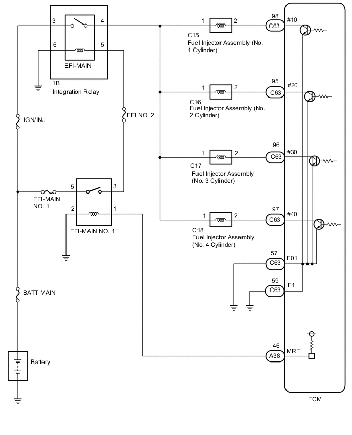
WIRING DIAGRAM
CAUTION / NOTICE / HINT
Note
Inspect the fuses for circuits related to this system before performing the following inspection procedure.
PROCEDURE
-
CHECK TERMINAL VOLTAGE (POWER SOURCE OF FUEL INJECTOR ASSEMBLY)
-
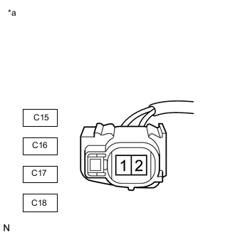
*a Front view of wire harness connector
(to Fuel Injector Assembly)
Disconnect the fuel injector assembly connectors.
-
Turn the ignition switch to ON.
-
Measure the voltage according to the value(s) in the table below.
Standard Voltage Tester Connection Switch Condition Specified Condition C15-1 - Body ground Ignition switch ON 11 to 14 V C16-1 - Body ground Ignition switch ON 11 to 14 V C17-1 - Body ground Ignition switch ON 11 to 14 V C18-1 - Body ground Ignition switch ON 11 to 14 V Result Proceed to OK NG
NG 
CHECK HARNESS AND CONNECTOR (FUEL INJECTOR ASSEMBLY - NO. 1 INTEGRATION RELAY) Click here
OK 
-
-
INSPECT FUEL INJECTOR ASSEMBLY
-
Inspect the fuel injector assembly.
Result Proceed to OK NG
NG 
REPLACE FUEL INJECTOR ASSEMBLY Click here
OK
-
-
CHECK HARNESS AND CONNECTOR (FUEL INJECTOR ASSEMBLY - ECM)
-
Disconnect the C63 ECM connector.
-
Disconnect the C15, C16, C17 and C18 fuel injector assembly connectors.
-
Measure the resistance according to the value(s) in the table below.
Standard Resistance Tester Connection Condition Specified Condition C15-2 - C63-98 (#10) Always Below 1 Ω C16-2 - C63-95 (#20) Always Below 1 Ω C17-2 - C63-96 (#30) Always Below 1 Ω C18-2 - C63-97 (#40) Always Below 1 Ω C15-2 or C63-98 (#10) - Body ground and other terminals Always 10 kΩ or higher C16-2 or C63-95 (#20) - Body ground and other terminals Always 10 kΩ or higher C17-2 or C63-96 (#30) - Body ground and other terminals Always 10 kΩ or higher C18-2 or C63-97 (#40) - Body ground and other terminals Always 10 kΩ or higher Result Proceed to OK NG
OK
PROCEED TO NEXT SUSPECTED AREA SHOWN IN PROBLEM SYMPTOMS TABLE Click here
NG
REPAIR OR REPLACE HARNESS OR CONNECTOR (FUEL INJECTOR ASSEMBLY - ECM)
-
-
CHECK HARNESS AND CONNECTOR (FUEL INJECTOR ASSEMBLY - NO. 1 INTEGRATION RELAY)
-
Disconnect the C15, C16, C17 and C18 fuel injector assembly connectors.
-
Disconnect the 1B No. 1 integration relay connector.
-
Measure the resistance according to the value(s) in the table below.
Standard Resistance Tester Connection Condition Specified Condition C15-1 - 1B-4 Always Below 1 Ω C16-1 - 1B-4 Always Below 1 Ω C17-1 - 1B-4 Always Below 1 Ω C18-1 - 1B-4 Always Below 1 Ω C15-1 or 1B-4 - Body ground and other terminals Always 10 kΩ or higher C16-1 or 1B-4 - Body ground and other terminals Always 10 kΩ or higher C17-1 or 1B-4 - Body ground and other terminals Always 10 kΩ or higher C18-1 or 1B-4 - Body ground and other terminals Always 10 kΩ or higher Result Result Proceed to OK A NG B
B
REPAIR OR REPLACE HARNESS OR CONNECTOR (FUEL INJECTOR ASSEMBLY - NO. 1 INTEGRATION RELAY)
A
-
-
CHECK TERMINAL VOLTAGE (POWER SOURCE OF NO. 1 INTEGRATION RELAY)
-
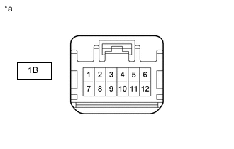
*a Rear view of wire harness connector (to No. 1 integration relay) Disconnect the No. 1 integration relay connector.
-
Measure the voltage according to the value(s) in the table below.
Standard Voltage Tester Connection Condition Specified Condition 1B-3 - Body ground Always 11 to 14 V Result Proceed to OK NG
NG
REPAIR OR REPLACE HARNESS OR CONNECTOR (NO. 1 INTEGRATION RELAY - BATTERY)
OK
-
-
CHECK HARNESS AND CONNECTOR (NO. 1 INTEGRATION RELAY - BODY GROUND)
-
*a Front view of wire harness connector (to No. 1 integration relay) Disconnect the No. 1 integration relay connector.
-
Measure the resistance according to the value(s) in the table below.
Standard Resistance Tester Connection Condition Specified Condition 1B-6 - Body ground Always Below 1 Ω Result Proceed to OK NG
NG
REPAIR OR REPLACE HARNESS OR CONNECTOR (NO. 1 INTEGRATION RELAY - BODY GROUND)
OK
-
-
INSPECT NO. 1 INTEGRATION RELAY
-
Inspect the No. 1 integration relay.
Result Proceed to OK NG
NG
REPLACE NO. 1 INTEGRATION RELAY Click here
OK
-
-
CHECK HARNESS AND CONNECTOR (EFI-MAIN NO. 1 - NO. 1 INTEGRATION RELAY)
-
Remove the EFI-MAIN NO. 1 relay from the No. 1 engine room relay block.
-
Disconnect the 1B No. 1 integration relay connector.
-
Measure the resistance according to the value(s) in the table below.
Standard Resistance Tester Connection Condition Specified Condition 3 (EFI-MAIN NO. 1 relay holder) - 1B-5 Always Below 1 Ω 3 (EFI-MAIN NO. 1 relay holder) or 1B-5 - Body ground and other terminals Always 10 kΩ or higher Result Result Proceed to OK A NG B
B
REPAIR OR REPLACE HARNESS OR CONNECTOR (EFI-MAIN NO. 1 - NO. 1 INTEGRATION RELAY)
A
-
-
CHECK TERMINAL VOLTAGE (POWER SOURCE OF EFI-MAIN NO. 1 RELAY)
-

*1 No. 1 Engine Room Relay Block *2 EFI-MAIN NO. 1 Relay Holder Remove the EFI-MAIN NO. 1 relay from the No. 1 engine room relay block.
-
Measure the voltage according to the value(s) in the table below.
Standard Voltage Tester Connection Condition Specified Condition 5 (EFI-MAIN NO. 1 relay holder) - Body ground Always 11 to 14 V Result Proceed to OK NG
NG
REPAIR OR REPLACE HARNESS OR CONNECTOR (EFI-MAIN NO. 1 RELAY - BATTERY)
OK
-
-
CHECK HARNESS AND CONNECTOR (EFI-MAIN NO. 1 RELAY - BODY GROUND)
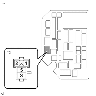
*1 No. 1 Engine Room Relay Block *2 EFI-MAIN NO. 1 Relay Holder
-
Remove the EFI-MAIN NO. 1 relay from the No. 1 engine room relay block.
-
Measure the resistance according to the value(s) in the table below.
Standard Resistance Tester Connection Condition Specified Condition 2 (EFI-MAIN NO. 1 relay holder) - Body ground Always Below 1 Ω Result Proceed to OK NG
NG
REPAIR OR REPLACE HARNESS OR CONNECTOR (EFI-MAIN NO. 1 RELAY - BODY GROUND)
OK
-
-
INSPECT EFI-MAIN NO. 1 RELAY
-
Inspect the EFI MAIN NO. 1 relay.
Result Proceed to OK NG
OK
PROCEED TO NEXT SUSPECTED AREA SHOWN IN PROBLEM SYMPTOMS TABLE Click here
NG
REPLACE EFI-MAIN NO. 1 RELAY
-