SIMPLE INTELLIGENT PARKING ASSIST SYSTEM Reverse Signal Circuit
| DTC Code | DTC Name |
|---|---|
| Reverse Signal Circuit |
DESCRIPTION
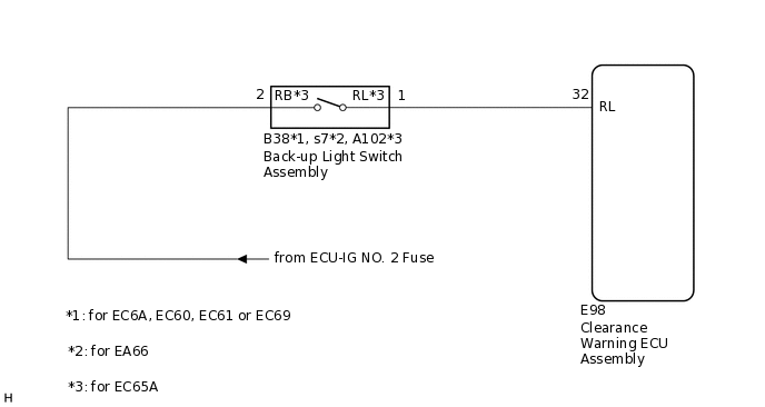
The clearance warning ECU assembly receives a reverse signal from the back-up light switch assembly. (for MT or MMT)
WIRING DIAGRAM
PROCEDURE
CHECK HARNESS AND CONNECTOR (REVERSE SIGNAL)
Disconnect the E98 clearance warning ECU assembly connector.
Measure the voltage according to the value(s) in the table below.
Standard Voltage
Tester Connection
Condition
Specified Condition
E98-32 (RL) - Body ground
Ignition switch ON, shift lever in R
11 to 14 V
Ignition switch ON, shift lever in any position other than R
Below 1 V
Result
Proceed to
OK
NG
CHECK HARNESS AND CONNECTOR (BACK-UP LIGHT SWITCH ASSEMBLY - CLEARANCE WARNING ECU ASSEMBLY)
Disconnect the E98 clearance warning ECU assembly connector.
Disconnect the B38*1, s7*2 or A102*3 back-up light switch assembly connector.
*1: for EC6A, EC60, EC61 or EC69
*2: for EA66
*3: for EC65A
Measure the resistance according to the value(s) in the table below.
Standard Resistance
Tester Connection
Condition
Specified Condition
E98-32 (RL) - B38-1*1
Always
Below 1 Ω
E98-32 (RL) - s7-1*2
Always
Below 1 Ω
E98-32 (RL) - A102-1 (RL)*3
Always
Below 1 Ω
E98-32 (RL) - Body ground
Always
10 kΩ or higher
*1: for EC6A, EC60, EC61 or EC69
*2: for EA66
*3: for EC65A
Result
Proceed to
OK
NG
NG REPAIR OR REPLACE HARNESS OR CONNECTOR
CHECK HARNESS AND CONNECTOR (BACK-UP LIGHT SWITCH ASSEMBLY POWER SOURCE)
Disconnect the B38*1, s7*2 or A102*3 back-up light switch assembly connector.
*1: for EC6A, EC60, EC61 or EC69
*2: for EA66
*3: for EC65A
Measure the voltage according to the value(s) in the table below.
Standard Voltage
Tester Connection
Condition
Specified Condition
B38-2 - Body ground*1
Ignition switch ON
11 to 14 V
s7-2 - Body ground*2
Ignition switch ON
11 to 14 V
A102-2 (RB) - Body ground*3
Ignition switch ON
11 to 14 V
*1: for EC6A, EC60, EC61 or EC69
*2: for EA66
*3: for EC65A
Result
Proceed to
OK
NG
OK REPLACE BACK-UP LIGHT SWITCH ASSEMBLY
for EC60:Click here
for EC61:Click here
for EC65A:Click hereClick here
for EA66:Click here
for EC69:Click hereClick here
for EC6A:Click here
NG REPAIR OR REPLACE HARNESS OR CONNECTOR