SFI SYSTEM(w/ Canister Pump Module), Diagnostic DTC:P166014
| DTC Code | DTC Name |
|---|---|
| P166014 | Air Intake Control Valve Circuit Short to Ground or Open |
DESCRIPTION
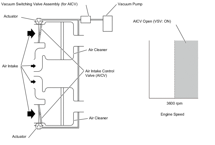
The air cleaner is equipped with two inlets, one of which is opened or closed by the Air Intake Control Valve (AICV). This system reduces intake noise and increases engine power at low-to-high engine speed range. When the engine is operating in the low-to-mid speed range, this control operates the AICV to close one of the air cleaner inlets. When the engine speed is more than 3600 rpm, the ECM activates VSV and opens the AICV.
| DTC No. | Detection Item | DTC Detection Condition | Trouble Area | MIL | Memory | Note |
|---|---|---|---|---|---|---|
| P166014 | Air Intake Control Valve Circuit Short to Ground or Open | Voltage of terminal air intake control valve of the ECM is low when the VSV is not operating for 3 seconds or more (1 trip detection logic). |
|
- | DTC stored | SAE: P1660 |
WIRING DIAGRAM
CAUTION / NOTICE / HINT
Note
Inspect the fuses for circuits related to this system before performing the following procedure.
Tech Tips
Read Freeze Frame Data using the GTS. The ECM records vehicle and driving condition information as Freeze Frame Data the moment a DTC is stored. When troubleshooting, Freeze Frame Data can help determine if the vehicle was moving or stationary, if the engine was warmed up or not, if the air fuel ratio was lean or rich, and other data from the time the malfunction occurred.
PROCEDURE
-
PERFORM ACTIVE TEST USING GTS (ACTIVATE THE VSV FOR AICS)
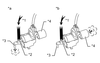
*1 Air *2 Port E *3 Port F *4 Air Filter *a Vacuum Switching Valve is On *b Vacuum Switching Valve is Off
-
Disconnect the vacuum hose (port F) from the vacuum switching valve assembly (for AICV).
-
Connect the GTS to the DLC3.
-
Turn the engine switch on (IG).
-
Turn the GTS on.
-
Enter the following menus: Powertrain / Engine / Active Test / Activate the VSV for AICS.
Powertrain > Engine > Active TestTester Display Activate the VSV for AICS -
Check the operation of the vacuum switching valve assembly (for AICV) when the vacuum switching valve assembly (for AICV) is operated using the GTS.
Standard GTS Connection Specified Condition ON Air from port E flows out through port F OFF Air from port E flows out through the air filter Result Proceed to OK NG
OK 
CHECK FOR INTERMITTENT PROBLEMS Click here
NG 
-
-
INSPECT VACUUM SWITCHING VALVE ASSEMBLY (FOR AICV)
-
Inspect the vacuum switching valve assembly (for AICV)
Result Proceed to OK NG
NG
REPLACE VACUUM SWITCHING VALVE ASSEMBLY (FOR AICV)
OK
-
-
CHECK TERMINAL VOLTAGE (POWER SOURCE OF VACUUM SWITCHING VALVE ASSEMBLY (FOR AICV))
-
Disconnect the vacuum switching valve assembly (for AICV) connector.
-
Turn the engine switch on (IG).
-
Measure the voltage according to the value(s) in the table below.
Standard Voltage Tester Connection Switch Condition Specified Condition D27-2 (+B) - Body ground Engine switch on (IG) 11 to 14 V Result Proceed to OK NG
NG 
INSPECT EFI-MAIN NO. 3 RELAY Click here
OK
-
-
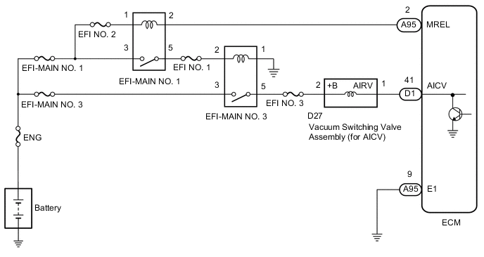
CHECK HARNESS AND CONNECTOR (VACUUM SWITCHING VALVE ASSEMBLY (FOR AICV) - ECM)
-
Disconnect the vacuum switching valve assembly (for AICV) connector.
-
Disconnect the ECM connector.
-
Measure the resistance according to the value(s) in the table below.
Standard Resistance Tester Connection Condition Specified Condition D27-1 (AIRV) - D1-41 (AICV) Always Below 1 Ω D27-1 (AIRV) or D1-41 (AICV) - Body ground Always 10 kΩ or higher Result Proceed to OK NG
OK
REPLACE ECM Click here
NG
REPAIR OR REPLACE HARNESS OR CONNECTOR
-
-
INSPECT EFI-MAIN NO. 3 RELAY
-
Inspect the EFI-MAIN NO. 3 relay.
Result Proceed to OK NG
NG
REPLACE EFI-MAIN NO. 3 RELAY
OK
-
-
CHECK HARNESS AND CONNECTOR (POWER SOURCE OF EFI-MAIN NO. 3 RELAY)
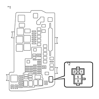
*1 Engine Room Relay Block and Junction Block Assembly *2 EFI-MAIN NO. 3 Relay
-
Remove the EFI-MAIN NO. 3 relay from the engine room relay block and junction block assembly.
-
Measure the voltage according to the value(s) in the table below.
Standard Voltage Tester Connection Condition Specified Condition 3 (EFI-MAIN NO. 3 relay) - Body ground Always 11 to 14 V Result Proceed to OK NG
NG
REPAIR OR REPLACE HARNESS OR CONNECTOR (BATTERY - EFI-MAIN NO. 3 RELAY)
OK
-
-
CHECK HARNESS AND CONNECTOR (EFI-MAIN NO. 3 RELAY - BODY GROUND)
-
Remove the EFI-MAIN NO. 3 relay from the engine room relay block and junction block assembly.
-
Measure the resistance according to the value(s) in the table below.
Standard Resistance Tester Connection Condition Specified Condition 1 (EFI-MAIN NO. 3 relay) - Body ground Always Below 1 Ω Result Proceed to OK NG
NG
REPAIR OR REPLACE HARNESS OR CONNECTOR
OK
-
-
CHECK HARNESS AND CONNECTOR (EFI-MAIN NO. 3 RELAY - VACUUM SWITCHING VALVE ASSEMBLY (FOR AICV))
-
Remove the EFI-MAIN NO. 3 relay from the No. 1 engine room relay block and junction block assembly.
Tech Tips
Remove the A/F HTR relay, VVT NO. 1 relay and VVT NO. 2 relay connected between the checked terminals as the coil inside the relay influences the measurement value.
-
Disconnect the vacuum switching valve assembly (for AICV) connector.
-
Measure the resistance according to the value(s) in the table below.
Standard Resistance Tester Connection Condition Specified Condition 5 (EFI-MAIN NO. 3 relay) - D27-2 (+B) Always Below 1 Ω 5 (EFI-MAIN NO. 3 relay) or D27-2 (+B) - Body ground and other terminals Always 10 kΩ or higher Result Proceed to OK NG
OK
REPAIR OR REPLACE HARNESS OR CONNECTOR (EFI-MAIN NO. 1 RELAY - EFI-MAIN NO. 3 RELAY)
NG
REPAIR OR REPLACE HARNESS OR CONNECTOR
-