CRUISE CONTROL SYSTEM(for 1ND-TV) TERMINALS OF ECU
CHECK DRIVING SUPPORT ECU ASSEMBLY

Terminal No. (Symbols)
Wiring Color
Terminal Description
Condition
Specified Condition
E128-30 (B) - E128-25 (GND)
B - BR
Battery
Always
11 to 14 V
E128-28 (ST1-) - E128-25 (GND)
R - BR*1
G - BR*2
Stop light switch signal
Ignition switch ON, Brake pedal released
11 to 14 V
Stop light switch signal
Ignition switch ON, Brake pedal released
Below 1 V
E128-27 (STP-) - E128-25 (GND)
L - BR
Stop light switch signal
Brake pedal released
Below 1 V
Brake pedal depressed
11 to 14 V
E128-25 (GND) - Body ground
BR
Earth (ground) circuit of driving support ECU assembly
Always
Below 1 Ω
E128-23 (CCS) - E128-25 (GND)
SB - BR*1
V - BR*2
Cruise control switch circuit
Ignition switch ON
1 MΩ or higher
Ignition switch ON, Cruise control switch on
Below 2.5 Ω
Ignition switch ON, +RES switch on
235 to 245 Ω
Ignition switch ON, -SET switch on
617 to 643 Ω
Ignition switch ON, CANCEL switch on
1509 to 1571 Ω
E128-17 (CH2L) - E128-25 (GND)
W - BR
CAN communication signal
Ignition switch ON
Pulse generation
(see waveform 1)
E128-39 (CH2H) - E128-25 (GND)
P - BR
CAN communication signal
Ignition switch ON
Pulse generation
(see waveform 2)
*1: for Hatchback, Wagon
*2: for Sedan
-
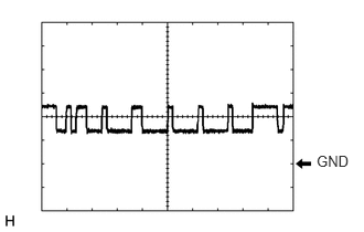
Waveform 1
CAN communication signal
Item
Content
Tester Connection
E128-17 (CH2L) - E128-25 (GND)
Tool Setting
1 V/DIV., 10 μsec./DIV.
Condition
Ignition switch ON
Tip:The waveform varies depending on the CAN communication signal.
-
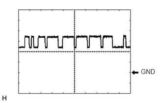
Waveform 2
CAN communication signal
Item
Content
Tester Connection
E128-39 (CH2H) - E128-25 (GND)
Tool Setting
1 V/DIV., 10 μsec./DIV.
Condition
Ignition switch ON
Tip:The waveform varies depending on the CAN communication signal.
-