NAVIGATION SYSTEM(for DVD) AVC-LAN Circuit
| DTC Code | DTC Name |
|---|---|
| AVC-LAN Circuit |
DESCRIPTION
Each unit of the navigation system connected to the AVC-LAN (communication bus) transfers switch signals by the audio visual communication local area network.
If a short to +B or short to ground occurs in the AVC-LAN, the navigation system does not function normally as communication stops.
WIRING DIAGRAM
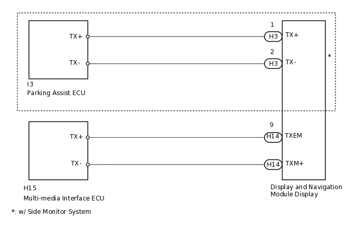
CAUTION / NOTICE / HINT
The display and navigation module display is the master unit.
PROCEDURE
INSPECT DISPLAY AND NAVIGATION MODULE DISPLAY
-
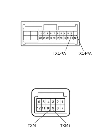
*A
w/ Side Monitor System
Remove the display and navigation module display.
Measure the resistance according to the value(s) in the table below.
Standard Resistance
Tester Connection
Condition
Specified Condition
1 (TX1+) - 2 (TX1-)*
Always
60 to 80 Ω
9 (TXM+) - 10 (TXM-)
Always
60 to 80 Ω
*: w/ Side Monitor System
Result
Result
OK
NG
-
CHECK HARNESS AND CONNECTOR (DISPLAY AND NAVIGATION MODULE DISPLAY - WHICH HAS STEREO THIS CODE)
Referring to the AVC-LAN wiring diagram above, check all AVC-LAN circuits.
Disconnect all connectors in all AVC-LAN circuits.
Check for an open or short in all AVC-LAN circuits.
OK
There is no open or short circuit.
Result
Result
OK
NG
NG REPAIR OR REPLACE HARNESS OR CONNECTOR
INSPECT MALFUNCTIONING PARTS
Disconnect and reconnect each slave unit one by one until the master unit returns to normal operation.
Tip:Check all slave units.
If disconnecting a slave unit causes the master unit to return to normal operation, the slave unit is defective and should be replaced.
OK
Master unit returns to normal operation.
Result
Result
OK
NG
OK REPLACE MALFUNCTIONING PARTS