CVT SYSTEM
-
FUNCTION OF MAIN COMPONENTS
Component Function Linear Solenoid Valve SLP (for Primary Pulley Control) Controls the oil pressure of the primary pulley in accordance with the vehicle speed and accelerator pedal opening angle to control the pulley ratio. Linear Solenoid Valve SLS (for Secondary Pulley Control) Controls the oil pressure of the secondary pulley in accordance with the input shaft torque to control the belt clamping force. Linear Solenoid Valve SLU (for Lock-up Control) Performs forward and reverse clutch control or lock-up clutch control depending on the state of the on-off solenoid valves SC and SL. On-off Solenoid Valve SC (for Clutch Control) Used to switch control of the linear solenoid valve SLU for forward and reverse clutch control. On-off Solenoid Valve SL (for Lock-up Control) Used to switch control of the linear solenoid valve SLU for lock-up clutch control. Transmission Revolution Sensor NIN Detects the primary pulley speed (input speed). Transmission Revolution Sensor NOUT Detects the secondary pulley speed (output speed). Transmission Revolution Sensor NT Detects the forward clutch drum speed (turbine speed). CVT Fluid Temperature Sensor Detects the CVT fluid temperature. Oil Pressure Sensor Detects the steel belt clamping force. Accelerator Pedal Sensor Assembly Detects the accelerator pedal opening angle. Throttle Position Sensor Detects the throttle valve opening angle. Intake Mass Air Flow Meter Sub-assembly Detects the intake air volume. Vacuum Sensor Assembly Detects the intake manifold pressure. Crank Position Sensor Detects the engine speed and performs cylinder identification. Engine Coolant Temperature Sensor Detects the engine coolant temperature. Park/Neutral Position Switch Assembly Detects the shift lever position. Transmission Control Switch
-
Detects that the shift lever is in M.
-
Detects the driver's shift-up and shift-down operations performed by the driver when the shift lever is in M.
Shift Paddle Switch (Transmission Shift Switch Assembly) Detects the shift-up and shift-down operations performed by the driver. Cruise Control Main Switch Turns the cruise control system on and off, and conducts various operations including vehicle speed setting, acceleration, deceleration and control cancellation. Stop Light Switch Assembly Detects the brake pedal depressing signal. Drive Mode Select
-
Outputs the NORMAL or SPORT mode signal to the ECM when operated by the driver.
-
Outputs the ECO mode signal to the ECM via the air conditioning amplifier assembly when operated by the driver.
ECM
-
Controls engine output and the electronic control of the CVT system.
-
Makes a diagnosis and memorizes the failed section when the ECM detects a malfunction.
Air Conditioning Amplifier Assembly Detects the air conditioning system operation. Combination Meter Assembly MIL Illuminates or blinks to inform the driver when the ECM detects a malfunction. Master Warning Light Warns the driver by lighting up when a message is shown on the multi-information display. Multi-information Display
-
Displays the shift lever position.
-
Displays the gear step (M1 to M8).
-
Displays the drive mode.
-
Warns the driver by displaying a message when the CVT fluid reaches a high temperature.
Multi Buzzer
-
Sounds when the shift-down operation is rejected.
-
Warns the driver by sounding when a message is shown on the multi-information display.
-
-
SYSTEM CONTROL
Electronic Control of CVT Control Outline Engine-CVT Integrated Control Performs coordinated control of the CVT system and engine control system to ensure both smooth and powerful driving that excels in shift response and fuel economy. Automatic Shift Control Controls the primary pulley speed to approach the target input rotation speed calculated based on the information such as the accelerator pedal opening angle, vehicle speed and brake signals. Acceleration Improvement Control* Controls the acceleration rate in proportion to the accelerator pedal position, improving the feeling of linear acceleration and expanding the feeling of accelerator pedal input. Deceleration Improvement Control* Determines a pulley ratio which allows for a high engine speed to be maintained during deceleration, ensuring adequate engine braking. Uphill/Downhill Shift Control Controls to restrict upshifts or to provide appropriate engine braking force by using the ECM to determine whether the vehicle is traveling uphill or downhill. Lock-up Control The ECM sends a current to the on-off solenoid valves SC and SL, and linear solenoid valve SLU based on the throttle position sensor signal and vehicle speed signal, and engages or disengages the lock-up clutch. Flex Lock-up Control By expanding the lock-up operation range into the low vehicle speed range, the fuel cut range has been enlarged, achieving improved fuel economy. 8-speed Sport Sequential Shiftmatic Enables driving in a gear step selected using the shift lever or shift paddle, providing engine braking force appropriate to each gear step. G AI-shift Control Helps to ensure the proper vehicle posture when entering a corner and ensures the driving torque when exiting a corner. *: Except models for china
-
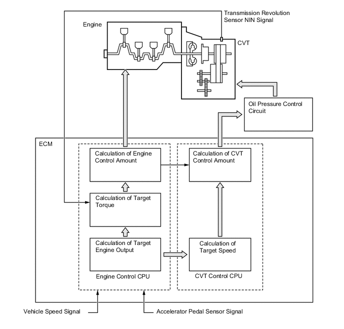
Engine-CVT Integrated Control
-
To perform fine-tuned control in accordance with driving conditions, various signals are exchanged between the engine control system and the CVT system. As a result, both smooth and powerful driving that excels in shift response and fuel economy has been achieved.
-
-
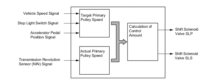
Automatic Shift Control (Speed Ratio Control)
-
The ECM calculates the target primary pulley speed in accordance with the accelerator pedal position signal, vehicle speed signal and stop light switch signal, in order to attain an optimal pulley ratio and shifting speed. To allow the actual primary pulley speed (acquired from the primary speed sensor) to match the target primary pulley speed, the ECM actuates the shift solenoid valves SLP and SLS in order to control the pressure of the primary pulley and secondary pulley. As a result, an optimal pulley ratio and shifting speed have been achieved.
-
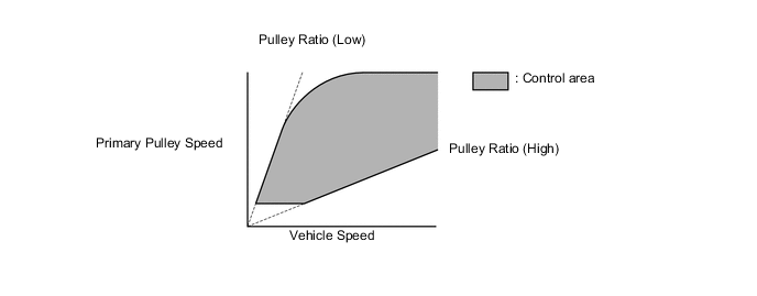
When the shift lever is in D, the system performs engine integrated control to optimize fuel economy characteristics and driving performance.
-
Extremely Economic Driving (when Cruising or Gently Accelerating/Decelerating) (Models for China)
-
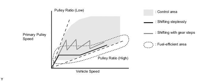
Shift control is performed to steplessly change the pulley ratio and ensure that the vehicle is driven at the most efficient engine speed, achieving excellent fuel economy.
-
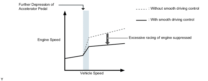
Smooth Driving (when Accelerating Moderately) (Models for China)
-
When the accelerator pedal is depressed, excessive racing of the engine is suppressed to minimize sudden starting off or acceleration, achieving a feeling of smooth acceleration even at low engine speeds and ensuring excellent fuel economy and quietness.
-
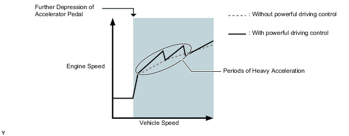
Powerful Driving (when Accelerating Rapidly) (Models for China)
-
When the accelerator pedal is depressed a large amount quickly, control is performed to allow the engine to race powerfully and exhilaratingly, delivering great acceleration and achieving a feeling of powerful driving.
-
-
The Sport mode limits the gear step for the acceleration side and maintains the primary pulley speed at high speeds. This produces a moderate engine braking force and provides an excellent shift response.
-
ECO mode changes the transmission characteristics to ones which prioritize fuel efficient driving to ensure low fuel consumption compared to those of NORMAL mode. This drive mode provides optimal fuel efficiency.
-
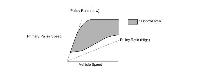
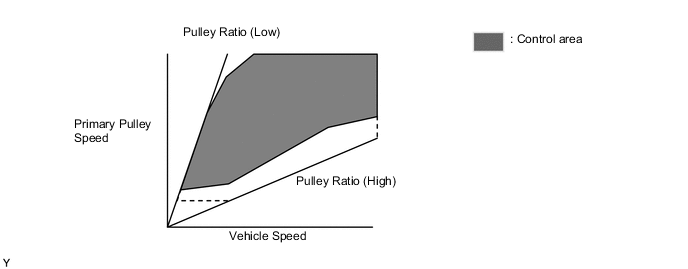
High-speed Rotation Pulley Ratio Pattern
-
By limiting shifting the pulley ratio to the high side, adequate engine braking force is generated during deceleration and an excellent response during reacceleration is achieved.
-
In addition, the engine speed increases more quickly during acceleration and a high engine speed is maintained, thus achieving a powerful drive while always maintaining a large driving force.
-
-
-
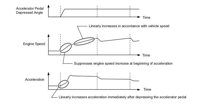
Acceleration Improvement Control (Except Models for China)
-
The system determines the driver's acceleration request based on the vehicle speed and the changes in the accelerator pedal position. When the system determines this request, it changes the shift characteristic into one in which the engine speed and vehicle speed increase linearly. This improves the acceleration feeling.
-
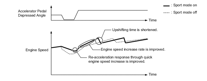
When Sport mode is on, upshifting time is shortened and the engine speed increase rate is improved, giving a sportier setting compared to when Sport mode is off.
-
-
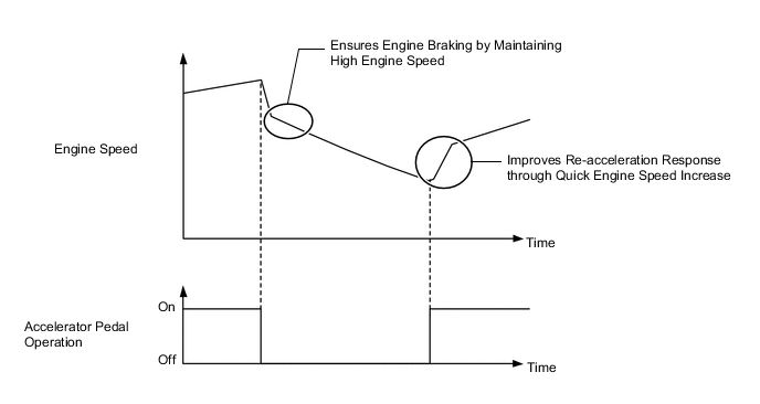
Deceleration Improvement Control (Except Models for China)
-
During deceleration, the pulley ratio is determined and a high engine speed is maintained, ensuring adequate engine braking.
-
Engine control, which generates driving force quickly, is conducted during re-acceleration.
-
-
Uphill/Downhill Shift Control
-
The ECM determines that the vehicle is driving uphill or downhill based on the accelerator pedal position sensor signal and the vehicle speed signal. During uphill driving, the ECM limits upshift to achieve smooth driving. During downhill driving, the ECM downshifts upon detecting brake pedal operation, in order to provide moderate engine braking.
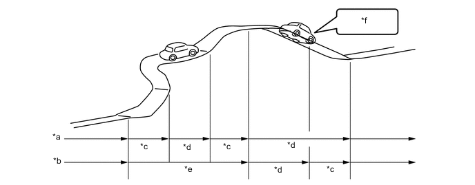
*a Without Control *b With Control *c Downshift *d Upshift *e Restrict Upshift *f Brake Operation -
The actual acceleration calculated from the vehicle speed signal is compared with the reference acceleration (based on level road travel) stored in the ECM to determine uphill or downhill travel.
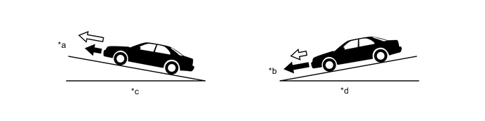
*a Smaller *b Greater *c Uphill *d Downhill 
Actual Acceleration 
Reference Acceleration
-
-
Lock-up Control
-
The lock-up operation range has been expanded from that of the previous continuously variable transaxle, enabling control to start from low speeds.
-
The lock-up operation range during deceleration has been expanded to the low-speed range. This expands the fuel cut range and achieves excellent fuel economy.
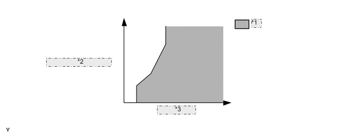
*1 Lock-up on *2 Throttle Opening Angle *3 Vehicle Speed
-
-
Flex Lock-up Control
-
In order to improve the transmission efficiency and also the fuel economy, the linear solenoid valve SLU for lock-up engagement pressure control is employed to deliver flex lock-up control that can provide more precise control than that of the conventional lock-up clutch mechanism.
-
The flex lock-up control consists of flex lock-up control during deceleration and flex start control.
-
Flex Lock-up Control during Deceleration
-
Flex lock-up control during deceleration is used to expand the fuel-cut range. It operates the lock-up clutch over the low vehicle speed range when the vehicle decelerates so that minimal speed difference between the engine speed and turbine speed can be maintained.
-
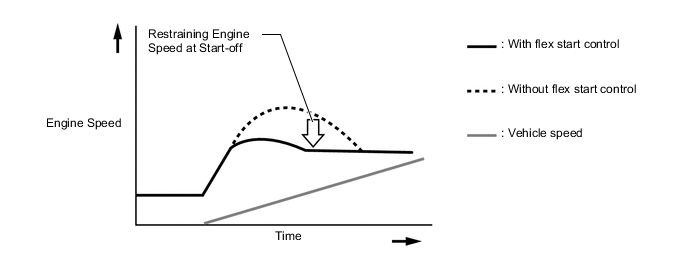
Flex Start Control
-
The flex start control aggressively operates the lock-up clutch during start-off to increase the transmission efficiency. As a result, the engine can run in its most efficient operating range.
-
-
-
8-speed Sport Sequential Shiftmatic
-
The 8-speed sport sequential shiftmatic is designed to allow the driver to switch the gear step. After moving the shift lever to M, the driver can select the desired gear step by moving the shift lever to "+" (upshift) or "-" (downshift). Thus, the driver is able to select gear steps with a manual-like feel. In addition, engine brake force can be obtained in accordance with each gear step.
-
The shift paddle can be used to change the gear step while the driver is holding the steering wheel.
-
Through engine-CVT integrated control, the pulley ratio and engine torque which correspond to shifting speed are finely controlled, improving shifting response and achieving a reduction in shifting shock.
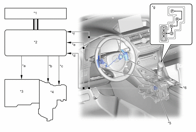
*1 Combination Meter Assembly
-
Shift Position Indicator
-
Multi Buzzer
*2 ECM *3 Engine *4 Transaxle *5 Transmission Control Switch *6 Shift Paddle Switch (Transmission Shift Switch Assembly) *a Engine Output Control Signal *b Oil Pressure Control Signal *c Pulley Ratio Control Signal *d M Mode Position Signal *e Shift-down Signal *f Shift-up Signal *g Shift Pattern - - -
-
When the shift lever is in M, this system automatically upshifts or downshifts under the following conditions:
Condition System Control Engine is under-revving. 1 step downshift Engine is over-revving. 1 step upshift -
When the vehicle is stopped while the shift lever is in M, the transaxle automatically downshifts to M1.
-
When the accelerator pedal is fully depressed and a kickdown operation is performed, a downshift to a gear step determined according to the vehicle speed is performed.
-
The ECM will restrict the changing of the gear step if it detects a malfunction in the CVT system.
-
If the vehicle speed and engine speed exceed or go below a preset level in response to the driver's downshift operation request, changing the gear step will be prohibited. In this case, the multi buzzer in the combination meter will sound to alert the driver.
-
When the shift lever is in D, the driver can momentarily select a desired gear step by operating the shift paddle. Automatic shift control is reverted to under the following conditions:
Condition System Control The driver continues to push the shift paddle in the "+" direction longer than a predetermined length of time. Reverts to automatic shift control The driver depresses the accelerator pedal longer than a predetermined length of time while the CVT remains in the same gear step. Reverts to automatic shift control The vehicle has stopped. Reverts to automatic shift control The driver has moved the shift lever to M. Transfers to manual shifting
-
-
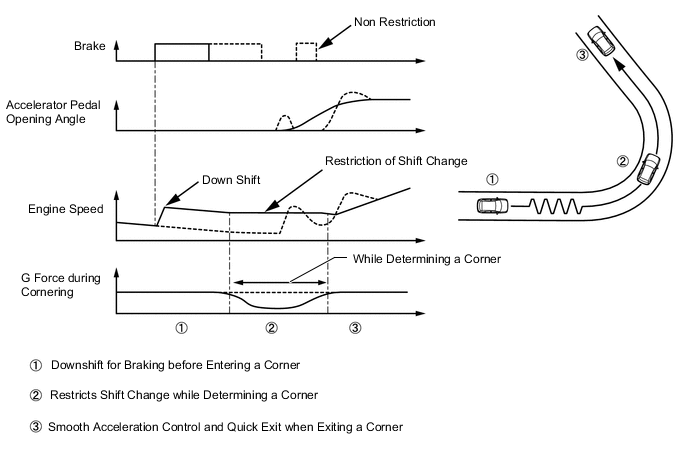
G AI-shift Control
-
G AI-shift control is used. When braking, G AI-shift control performs braking downshift in accordance with the actual braking force, producing appropriate engine braking force. Additionally, while determining a corner condition, G AI-shift control restricts unnecessary shift change and maintains the engine speed by detecting a lateral G force, improving acceleration control performance and ensuring the drive torque when exiting a corner.
Tech Tips
-
G AI-shift control is turned on by pressing the Sport mode switch. When Sport mode is selected, the Sport mode indicator light in the combination meter assembly illuminates. Pressing the Sport mode switch again turns Sport mode off.
-
When the engine is stopped with Sport mode on, Sport mode is turned off.
-
When the shift lever is in M or temporary sport sequential shiftmatic mode is selected, gear range change operation due to mode change is not performed.
-
If a malfunction is detected in the CVT system, transmission control is performed in normal mode.
-
-
-
-
FUNCTION
-
Drive Mode Select
-
The motive force characteristics for the accelerator opening angle can be changed through the selection of the drive mode according to driver preference.
-
The drive mode can be switched by turning the dial type drive mode select. In addition, the vehicle can be returned to NORMAL mode by pressing the drive mode select.
-
An indicator is provided in the combination meter assembly and the drive mode the driver selected can be recognized.
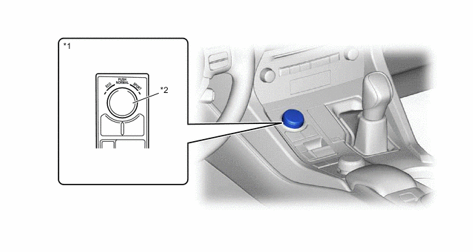
*1 Integration Control and Panel Assembly *2 Drive Mode Select Characteristics of Drive Mode Drive Mode Characteristics NORMAL Mode This drive mode provides optimum driveability. ECO Mode The ECM optimizes fuel economy and driving performance by gradually generating the motive force in comparison to the accelerator pedal operation. At the same time, the ECM supports eco driving by optimizing air conditioning performance. SPORT Mode The ECM controls motive force in the intermediate area of the accelerator pedal opening to a greater degree than that of NORMAL mode, improving acceleration performance. In addition, engine speed response performance has been improved in the high area of the accelerator pedal opening, producing a sporty drive.
-
-
-
FAIL-SAFE
-
This function minimizes the loss of operability when any abnormality occurs in any sensor or shift solenoid valve.
-
For details, refer to the Repair Manual.
-
-
DIAGNOSIS
-
When the ECM detects a malfunction, it makes a diagnosis and memorizes the failed section. Furthermore, the MIL in the combination meter illuminates or blinks to inform the driver.
-
At the same time, the Diagnostic Trouble Codes (DTCs) are stored in memory. The DTCs can be read by connecting a Global TechStream (GTS). For details, refer to the Repair Manual.
-