FRONT STABILIZER BAR REMOVAL
CAUTION / NOTICE / HINT
The necessary procedures (adjustment, calibration, initialization, or registration) that must be performed after parts are removed and installed, or replaced during front stabilizer bar removal/installation are shown below.
| Replaced Part or Performed Procedure | Necessary Procedure | Effect/Inoperative Function when Necessary Procedure not Performed | Link |
|---|---|---|---|
| Battery terminal is disconnected/reconnected | Perform steering sensor zero point calibration | Lane departure alert system (w/ Steering Control) | |
| Pre-collision system | |||
| Memorize steering angle neutral point | Parking assist monitor system | ||
| Replacement of ECM | Vehicle Identification Number (VIN) registration | MIL comes on | for 2AR-FE: Click here for A25A-FKS (w/ Canister Pump Module): Click here for A25A-FKS (w/o Canister Pump Module): Click here for 2GR-FKS: Click here |
| Perform code registration (Immobiliser system) | Engine start function | See Service Bulletin for the registration method. | |
|
Inspection After Repair |
|
for 2AR-FE: Click here for A25A-FKS (w/ Canister Pump Module): Click here for A25A-FKS (w/o Canister Pump Module): Click here for 2GR-FKS: Click here |
| Replacement of automatic transaxle assembly |
|
|
for UA80E Initialization: Click here for UA80E Registration: Click here for UB80E Initialization: Click here for UB80E Registration: Click here for U760E Initialization: Click here for U760E Registration: Click here |
| Replacement of ECM (If possible, read the transaxle compensation code from the previous ECM) |
|
||
| Replacement of ECM (If impossible, read the transaxle compensation code from the previous ECM) |
|
||
| Replacement of ECM | Perform code registration (Immobiliser function) |
|
See Service Bulletin for the registration method. |
| Suspension, tires, etc. (The vehicle height changes because of suspension or tire replacement) |
Rear television camera assembly optical axis (Back camera position setting) | Parking assist monitor system | for Initialization: Click here for Calibration: Click here |
| Perform headlight ECU sub-assembly LH initialization | Lighting system (EXT) (w/ Automatic Headlight Beam Level Control System) | ||
| Front wheel alignment adjustment | Perform system variant learning and acceleration sensor zero point calibration. |
|
|
| Rack and pinion power steering gear assembly |
|
|
PROCEDURE
-
REMOVE ENGINE ASSEMBLY WITH TRANSAXLE
for 2AR-FE: Click here
for A25A-FKS: Click here
for 2GR-FKS: Click here
-
REMOVE FRONT STABILIZER LINK ASSEMBLY LH
-
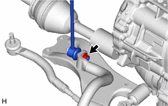
Remove the nut and front stabilizer link assembly LH from the front stabilizer bar.
Note
Do not damage the boot of the ball joint.
Tech Tips
If the ball joint turns together with the nut, use a 6 mm hexagon socket wrench to hold the stud bolt.
-
-
REMOVE FRONT STABILIZER LINK ASSEMBLY RH
Tech Tips
Perform the same procedure as for the LH side.
-
REMOVE FRONT NO. 1 STABILIZER BRACKET LH
-
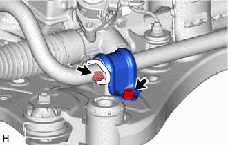
Remove the 2 bolts and front No. 1 stabilizer bracket LH from the front frame assembly.
-
-
REMOVE FRONT NO. 1 STABILIZER BRACKET SUB-ASSEMBLY RH (for A25A-FKS)
-
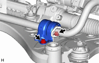
Remove the 2 bolts and front No. 1 stabilizer bracket sub-assembly RH from the front frame assembly.
-
-
REMOVE FRONT NO. 1 STABILIZER BRACKET RH (for 2AR-FE, 2GR-FKS)
Tech Tips
Perform the same procedure as for the LH side.
-
REMOVE FRONT STABILIZER BAR
-
Remove the front stabilizer bar with 2 front stabilizer bar bushings from the front frame assembly.
-
-
REMOVE FRONT NO. 1 STABILIZER BAR BUSHING (for LH Side)
-
Remove the front No. 1 stabilizer bar bushing from the front stabilizer bar.
-
-
REMOVE FRONT NO. 1 STABILIZER BAR BUSHING (for RH Side)
Tech Tips
Perform the same procedure as for the LH side.