STEERING PAD SWITCH INSPECTION
PROCEDURE
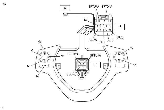
INSPECT STEERING PAD SWITCH ASSEMBLY
Measure the resistance according to the value(s) in the table below.
*A
w/ Shift Paddle Switch
-
-
*a
Component without harness connected
(Steering Pad Switch Assembly)
*b
Volume+
*c
Volume-
*d
MODE
*e
Seek+
*f
Seek-
*g
Off hook
*h
On hook
Standard Resistance
Tester Connection
Condition
Specified Condition
z1-1 (HO) - A-1 (HO)
Always
Below 2.5 Ω
z1-10 (AU1) - z1-8 (EAU)
No switch pushed
95 to 105 kΩ
Seek+ switch pushed
Below 2.5 Ω
Seek- switch pushed
313 to 345 Ω
Volume+ switch pushed
950 to 1050 Ω
Volume- switch pushed
2955 to 3265 Ω
z1-9 (AU2) - z1-8 (EAU)
No switch pushed
95 to 105 kΩ
MODE switch pushed
Below 2.5 Ω
On hook switch pushed
313 to 345 Ω
Off hook switch pushed
950 to 1050 Ω
z1-2 (SFTU) - z6-2 (SFTU)*
Always
Below 2.5 Ω
z1-3 (SFTD) - z6-3 (SFTD)*
Always
Below 2.5 Ω
z1-6 (ECC) - z6-7 (ECC)*
Always
Below 2.5 Ω
*: w/ Shift Paddle Switch
Tip:If the result is not as specified, replace the steering pad switch assembly.