POWER STEERING SYSTEM
-
CONSTRUCTION
-
The power steering torque sensor is built into the steering column assembly. The power steering torque sensor consists of a detection ring, a stub shaft and 2 detection coils.
-
The detection ring is mounted on the input shaft and the stub shaft is mounted on the output shaft. The input shaft and the output shaft are joined by the torsion bar. The detection coils are placed on the outside of the detection ring to complete an excitation circuit without making contact.
-
When the steering wheel is turned, the twist that is created in the torsion bar creates a relative displacement between the detection ring and the stub shaft. The torque sensor outputs this change as an electrical signal to the power steering ECU assembly.
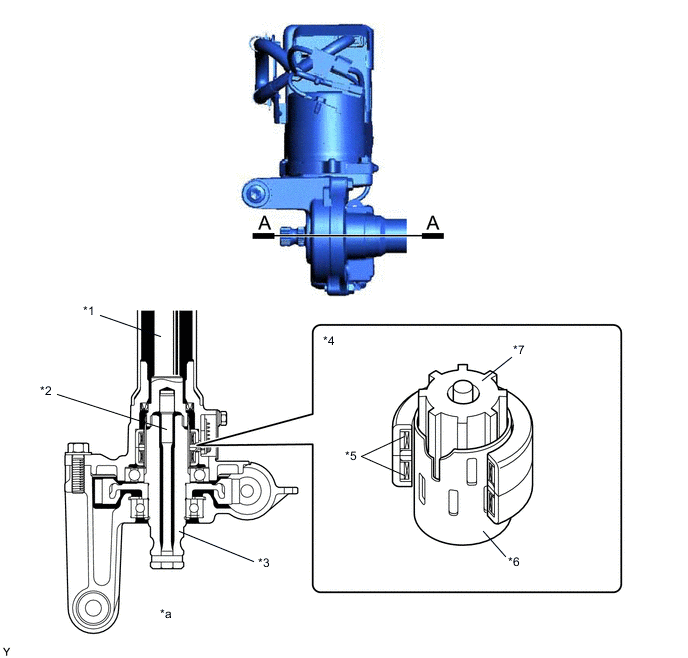
*1 Input Shaft *2 Torsion Bar *3 Output Shaft *4 Power Steering Torque Sensor *5 Detection Coil *6 Detection Ring *7 Stub Shaft - - *a A - A Cross Section - -
-
-
OPERATION
-
The torque detection circuit built into the power steering ECU assembly calculates the torque sensor 1 output (VT1) and the torque sensor 2 output (VT2) in accordance with the signals from the 2 detection coils of the torque sensor.
-
The power steering ECU assembly detects the steering torque and the steering direction in accordance with VT1 and VT2.
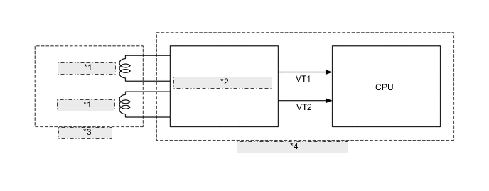
*1 Detection Coil *2 Torque Detection Circuit *3 Torque Sensor *4 Power Steering ECU Assembly -
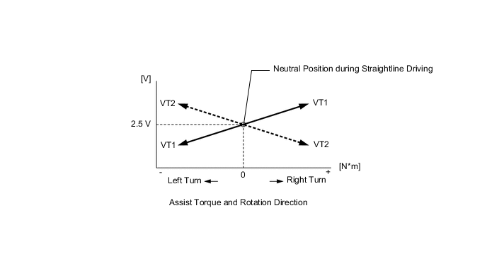
When the driver does not turn the steering wheel, VT1 and VT2 output a specified voltage (approximately 2.5 V). As long as the specified voltage is output, the power steering ECU assembly determines that steering torque is not being generated.
-
When the driver turns the steering wheel to the right or left, VT1 and VT2 change as shown in the graph below. Based on the changes, the power steering ECU assembly determines the steering torque and steering direction input by the driver.
-