SFI SYSTEM, Diagnostic DTC:P0805,P0806,P0807,P0808 and P0831
| DTC Code | DTC Name |
|---|---|
| P0805 | Clutch Position Sensor "A" Circuit |
| P0806 | Clutch Position Sensor "A" Circuit Range / Performance |
| P0807 | Clutch Position Sensor "A" Circuit Low |
| P0808 | Clutch Position Sensor "A" Circuit High |
| P0831 | Clutch Pedal Switch "A" Circuit Low |
DESCRIPTION
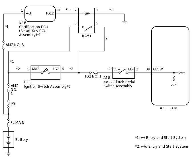
The No. 2 clutch pedal switch assembly is mounted on the clutch pedal. The switch is turned off when depressing the clutch pedal, and transmits a signal to the ECM.
DTC No. |
Detection Item |
DTC Detection Condition |
Trouble Area |
MIL |
Memory |
|---|---|---|---|---|---|
P0805 |
Clutch Position Sensor "A" Circuit |
Abnormal No. 2 clutch pedal switch assembly signal input to ECM. |
|
Does not come on |
DTC stored |
P0806 |
Clutch Position Sensor "A" Circuit Range / Performance |
Abnormal No. 2 clutch pedal switch assembly signal input to ECM. |
|
Does not come on |
DTC stored |
P0807 |
Clutch Position Sensor "A" Circuit Low |
Short to ground in No. 2 clutch pedal switch assembly circuit. |
|
Does not come on |
DTC stored |
P0808 |
Clutch Position Sensor "A" Circuit High |
Short to +B in No. 2 clutch pedal switch assembly circuit. |
|
Does not come on |
DTC stored |
P0831 |
Clutch Pedal Switch "A" Circuit Low |
No. 2 clutch pedal switch assembly signal does not change when vehicle speed signal is input. |
|
Does not come on |
DTC stored |
MONITOR DESCRIPTION
These DTCs are stored when a malfunction is detected in the No. 2 clutch pedal switch assembly circuit. If there is an open or short in the No. 2 clutch pedal switch assembly circuit or the No. 2 clutch pedal switch assembly signal does not change when the vehicle is being driven, the ECM will store a DTC.
WIRING DIAGRAM
CAUTION / NOTICE / HINT
Inspect the fuses for circuits related to this system before performing the following procedure.
PROCEDURE
INSPECT NO. 2 CLUTCH PEDAL SWITCH ASSEMBLY
Inspect the No. 2 clutch pedal switch assembly.
Result
Proceed to
OK
NG
CHECK SWITCH INSTALLATION (NO. 2 CLUTCH PEDAL SWITCH ASSEMBLY)
Check the No. 2 clutch pedal switch assembly installation.
OK
The switch is installed correctly.
Result
Proceed to
OK
NG
CHECK TERMINAL VOLTAGE (POWER SOURCE OF NO. 2 CLUTCH PEDAL SWITCH ASSEMBLY)
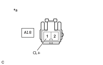
*a
Front view of wire harness connector
(to No. 2 Clutch Pedal Switch Assembly)
Disconnect the No. 2 clutch pedal switch assembly connector.
Turn the ignition switch to ON.
Measure the voltage according to the value(s) in the table below.
Standard Voltage
Tester Connection
Condition
Specified Condition
A18-1 (CL+) - Body ground
Ignition switch ON
11 to 14 V
Result
Result
Proceed to
OK
A
NG (w/ Entry and Start System)
B
NG (w/o Entry and Start System)
C
B REPAIR OR REPLACE HARNESS OR CONNECTOR (NO. 2 CLUTCH PEDAL SWITCH ASSEMBLY - IG2 RELAY)
C REPAIR OR REPLACE HARNESS OR CONNECTOR (NO. 2 CLUTCH PEDAL SWITCH ASSEMBLY - IGNITION SWITCH ASSEMBLY)
CHECK HARNESS AND CONNECTOR (NO. 2 CLUTCH PEDAL SWITCH ASSEMBLY - ECM)
Disconnect the No. 2 clutch pedal switch assembly connector.
Disconnect the ECM connector.
Measure the resistance according to the value(s) in the table below.
Standard Resistance
Tester Connection
Condition
Specified Condition
A18-2 (CL-) - A35-39 (CLSW)
Always
Below 1 Ω
A18-2 (CL-) or A35-39 (CLSW) - Body ground and other terminals
Always
10 kΩ or higher
Result
Proceed to
OK
NG
NG REPAIR OR REPLACE HARNESS OR CONNECTOR