CRUISE CONTROL SYSTEM Clutch Switch Circuit
DESCRIPTION
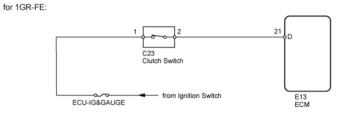
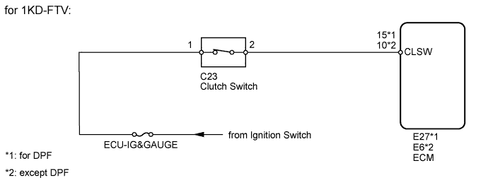
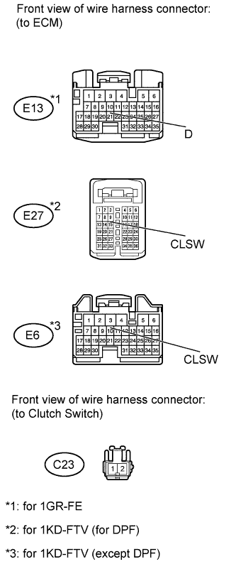
When the clutch pedal is released, the ECM receives positive (+) battery voltage through the ECU-IG&GAUGE fuse. While depressing the clutch pedal, the clutch switch sends a signal to terminal 21(D)*1, 15(CLSW)*2 or 10(CLSW)*3 of the ECM. The ECM cancels cruise control when terminal 21(D)*1, 15(CLSW)*2 or 10(CLSW)*3 receives the signal.
-
*1: for 1GR-FE
-
*2: for 1KD-FTV (for DPF)
-
*3: for 1KD-FTV (except DPF)
WIRING DIAGRAM
INSPECTION PROCEDURE
PROCEDURE
-
INSPECT FUSE (ECU-IG&GAUGE)
-
Remove the ECU-IG&GAUGE fuse from the driver side junction block.
-
Measure the resistance according to the value(s) in the table below.
Standard Resistance Tester Connection Condition Specified Condition ECU-IG&GAUGE fuse Always Below 1 Ω
NG 
REPLACE FUSE
OK 
-
-
CHECK HARNESS AND CONNECTOR (ECM - BATTERY)
-
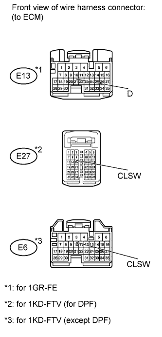
Disconnect the E13*1, E27*2 or E6*3 ECM connector.
*1: for 1GR-FE
*2: for 1KD-FTV (for DPF)
*3: for 1KD-FTV (except DPF)
-
Measure the voltage according to the value(s) in the table below.
Standard Voltage for 1GR-FE Tester Connection Switch Condition Specified Condition E13-21 (D) - Body ground Ignition switch ON
Clutch pedal depressed
Below 1 V Ignition switch ON
Clutch pedal released
11 to 14 V for 1KD-FTV (for DPF) Tester Connection Switch Condition Specified Condition E27-15 (CLSW) - Body ground Ignition switch ON
Clutch pedal depressed
Below 1 V Ignition switch ON
Clutch pedal released
11 to 14 V for 1KD-FTV (except DPF) Tester Connection Switch Condition Specified Condition E6-10 (CLSW) - Body ground Ignition switch ON
Clutch pedal depressed
Below 1 V Ignition switch ON
Clutch pedal released
11 to 14 V
NG 
INSPECT CLUTCH SWITCH ASSEMBLY Click here
OK 
PROCEED TO NEXT CIRCUIT INSPECTION SHOWN IN PROBLEM SYMPTOMS TABLE
-
-
INSPECT CLUTCH SWITCH ASSEMBLY
-
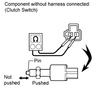
Remove the clutch switch.
-
Measure the resistance according to the value(s) in the table below.
Standard Resistance Tester Connection Switch Condition Specified Condition 1 - 2 Pin pushed Below 1 Ω Pin not pushed 10 kΩ or higher
NG
REPLACE CLUTCH SWITCH ASSEMBLY
OK
-
-
CHECK HARNESS AND CONNECTOR (ECM - CLUTCH SWITCH)
-
Disconnect the E13*1, E27*2 or E6*3 ECM connector.
*1: for 1GR-FE
*2: for 1KD-FTV (for DPF)
*3: for 1KD-FTV (except DPF)
-
Disconnect the C23 clutch switch connector.
-
Measure the resistance according to the value(s) in the table below.
Standard Resistance for 1GR-FE Tester Connection Condition Specified Condition E13-21 (D) - C23-2 Always Below 1 Ω E13-21 (D) - Body ground Always 10 kΩ or higher for 1KD-FTV (for DPF) Tester Connection Condition Specified Condition E27-15 (CLSW) - C23-2 Always Below 1 Ω E27-15 (CLSW) - Body ground Always 10 kΩ or higher for 1KD-FTV (except DPF) Tester Connection Condition Specified Condition E6-10 (CLSW) - C23-2 Always Below 1 Ω E6-10 (CLSW) - Body ground Always 10 kΩ or higher
NG
REPAIR OR REPLACE HARNESS OR CONNECTOR (ECM - CLUTCH SWITCH)
OK
REPAIR OR REPLACE HARNESS OR CONNECTOR (BATTERY - CLUTCH SWITCH)
-