REAR COIL SPRING(for Torsion Beam Type Suspension) INSTALLATION
CAUTION / NOTICE / HINT
Use the same procedure for the RH side and LH side.
The procedure listed below is for the LH side.
PROCEDURE
INSTALL REAR UPPER COIL SPRING INSULATOR
-
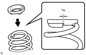
*a
10 mm or less
Install the rear upper coil spring insulator to the rear coil spring.
Note:Install the rear upper coil spring insulator so that the dimension between the stopper and upper end of the rear coil spring is 10 mm (0.394 in.) or less.
-
INSTALL REAR LOWER COIL SPRING INSULATOR
Install the rear lower coil spring insulator to the rear axle beam assembly.
INSTALL REAR COIL SPRING
Support the spring seat of the rear axle beam assembly using 2 jacks and 2 wooden blocks.
Remove the 2 bolts while holding the 2 nuts and separate the rear axle beam assembly from the rear shock absorber assemblies LH and RH.
Note:Because the nuts have their own stoppers, do not turn the nuts. Loosen the bolts with the nuts secured.
Slowly lower the rear axle beam assembly using 2 jacks and 2 wooden blocks.
-
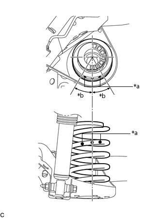
*a
Identification Mark
*b
30° or less
Set the rear coil spring to the rear axle beam assembly.
Note:Set the rear coil spring so that the identification marks are positioned as shown in the illustration.
Slowly jack up the rear axle beam assembly using 2 jacks and 2 wooden blocks, and temporarily install the rear axle beam assembly and rear coil spring with the 2 bolts and 2 nuts.
Note:Because the nuts have their own stoppers, do not turn the nuts. Tighten the bolts with the nuts secured.
Tip:Insert the bolt with the threaded end facing the outside of the vehicle.
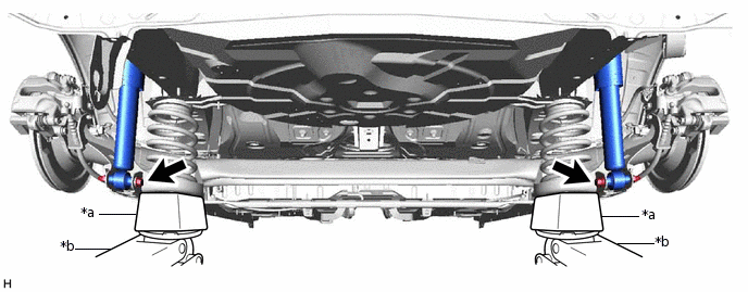
*a
Wooden Block
*b
Jack
INSTALL REAR HEIGHT CONTROL SENSOR SUB-ASSEMBLY (w/ Height Control Sensor)
Install the rear height control sensor sub-assembly to the rear axle beam assembly with the bolt.
8.0 N*m
82 kgf*cm
71 in.*lbf
INSTALL SKID CONTROL SENSOR WIRE LH
Install the skid control sensor wire LH to the rear axle beam assembly with the nut and 2 clamps.
8.5 N*m
87 kgf*cm
75 in.*lbf
Note:Do not twist the skid control sensor wire when installing it.
Connect the skid control sensor wire LH connector.
INSTALL SKID CONTROL SENSOR WIRE RH
Tip:Perform the same procedure as the LH side.
INSTALL REAR WHEELS
103 N*m
1050 kgf*cm
76 ft.*lbf
STABILIZE SUSPENSION
FULLY TIGHTEN REAR AXLE BEAM ASSEMBLY
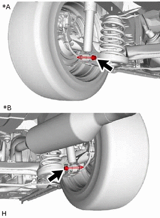
-
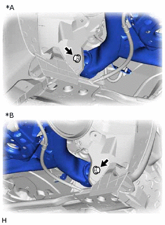
*A
LH Side
*B
RH Side
Fully tighten the 2 rear axle beam assembly bolts.
135 N*m
1377 kgf*cm
100 ft.*lbf
-
*A
LH Side
*B
RH Side
Fully tighten the 2 rear shock absorber assembly bolts.
90 N*m
918 kgf*cm
66 ft.*lbf
Note:Because the nuts have their own stoppers, do not turn the nuts. Tighten the bolts with the nuts secured.
-
INSTALL REAR WHEEL HOUSE LINER LH (w/ Wheel House Liner)
Install the rear wheel house liner LH with the clip.
INSTALL REAR WHEEL HOUSE LINER RH (w/ Wheel House Liner)
Tip:Perform the same procedure as the LH side.
INSPECT REAR WHEEL ALIGNMENT
CHECK FOR SPEED SENSOR SIGNAL