FRONT AXLE HUB INSTALLATION
CAUTION / NOTICE / HINT
Use the same procedure for the RH and LH sides.
The procedure listed below is for the LH side.
PROCEDURE
INSTALL FRONT AXLE HUB SUB-ASSEMBLY LH
Secure the steering knuckle in a vise.
Note:When using a vise, do not overtighten it.
Install the front brake dust cover to the steering knuckle.
Install the front axle hub sub-assembly LH with the 4 bolts.
96 N*m
979 kgf*cm
71 ft.*lbf
Note:Do not place the hub and bearing's magnet rotor side so that it is facing downward, and do not allow the magnet rotor side to become damaged or contact foreign matter.
INSTALL FRONT AXLE ASSEMBLY LH
-
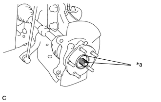
*a
Matchmark
Align the matchmarks and install the front drive shaft assembly to the front axle assembly LH.
-
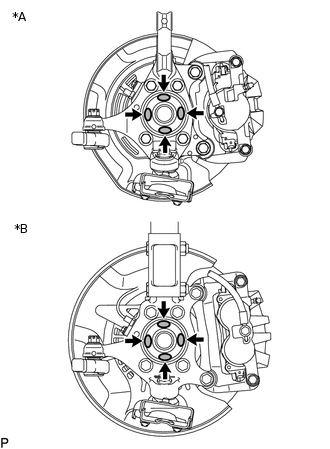
*A
for 16 inch Front Disc Brake
*B
for 17 inch Front Disc Brake
Apply MP grease to the entire contact surface between the front drive shaft assembly and axle hub bearing surface or only apply 0.1 to 0.3 g (0.00353 to 0.0105 oz.) of MP grease to the 4 areas on the axle hub bearing shown in the illustration.
Install the front axle assembly LH to the front shock absorber assembly with coil spring with the 2 bolts and 2 nuts.
240 N*m
2447 kgf*cm
177 ft.*lbf
Note:Be careful not to damage the drive shaft boot and speed sensor rotor.
Do not tighten the bolts.
-
CONNECT FRONT LOWER NO. 1 SUSPENSION ARM SUB-ASSEMBLY LH
CONNECT TIE ROD END SUB-ASSEMBLY LH
INSTALL FRONT DISC
for 16 inch Front Disc Brake:Click here
for 17 inch Front Disc Brake:Click here
CONNECT FRONT DISC BRAKE CALIPER ASSEMBLY LH
TEMPORARILY INSTALL FRONT AXLE SHAFT NUT LH
Clean the threaded parts on the drive shaft and a new axle shaft nut LH using a non-residue solvent.
Note:Be sure to perform this work for a new drive shaft.
Keep the threaded parts free of oil and foreign objects.
-
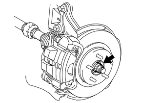
Using a 30 mm socket wrench, temporarily install the axle shaft nut LH.
292 N*m
2978 kgf*cm
215 ft.*lbf
Tip:Stake the nut after inspecting for looseness and runout in the following steps.
DISCONNECT FRONT DISC BRAKE CALIPER ASSEMBLY LH
REMOVE FRONT DISC
for 16 inch Front Disc Brake:Click here
for 17 inch Front Disc Brake:Click here
INSPECT FRONT AXLE HUB BEARING LOOSENESS
INSPECT FRONT AXLE HUB RUNOUT
INSTALL FRONT DISC
for 16 inch Front Disc Brake:Click here
for 17 inch Front Disc Brake:Click here
CONNECT FRONT DISC BRAKE CALIPER ASSEMBLY LH
CONNECT FRONT FLEXIBLE HOSE
CONNECT FRONT SPEED SENSOR LH
Connect the front speed sensor LH and front flexible hose to the front shock absorber with the bolt and clamp.
29 N*m
296 kgf*cm
21 ft.*lbf
Note:Do not twist the front speed sensor when installing it.
Tip:Install the front flexible hose first and then the speed sensor harness bracket.
Install the front speed sensor LH to the steering knuckle with the bolt.
8.5 N*m
87 kgf*cm
75 in.*lbf
Note:Do not twist the front speed sensor when installing it.
INSTALL FRONT AXLE SHAFT NUT LH
-
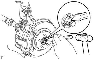
Using a chisel and hammer, stake the front axle shaft nut LH.
-
INSTALL FRONT WHEEL
CONNECT CABLE TO NEGATIVE AUXILIARY BATTERY TERMINAL
Connect the cable to the negative (-) auxiliary battery terminal and tighten the nut.
5.4 N*m
55 kgf*cm
48 in.*lbf
PERFORM INITIALIZATION
INSPECT AND ADJUST FRONT WHEEL ALIGNMENT
CHECK FOR SPEED SENSOR SIGNAL