COOLING FAN SYSTEM Cooling Fan Circuit
| DTC Code | DTC Name |
|---|---|
| Cooling Fan Circuit |
DESCRIPTION
The ECM turn on or off the FAN NO. 1 relay using signals calculated from the engine coolant temperature, air conditioning, air conditioner refrigerant pressure, engine speed and vehicle speed signals.
WIRING DIAGRAM
Refer to the System Diagram.
CAUTION / NOTICE / HINT
Inspect the fuses for circuits related to this system before performing the following procedure.
PROCEDURE
PERFORM ACTIVE TEST USING GTS (CONTROL THE ELECTRIC COOLING FAN)
Connect the GTS to the DLC3.
Turn the ignition switch to ON.
Turn the GTS on.
Enter the following menus: Powertrain / Engine and ECT / Active Test / Control the Electric Cooling Fan.
Check the operation of the cooling fan while operating it using the GTS.
Powertrain > Engine and ECT > Active Test
Tester Display
Control the Electric Cooling Fan
OK
GTS Operation
Fan Operation
ON
Cooling fan operates
OFF
Cooling fan stops
Result
Result
Proceed to
OK
A
NG (Cooling fan does not operate)
B
NG (Cooling fan does not stop)
C
C CHECK HARNESS AND CONNECTOR (FAN NO. 1 RELAY - ECM)Click here
INSPECT COOLING FAN MOTOR
Inspect the cooling fan motor.
Result
Proceed to
OK
NG
CHECK TERMINAL VOLTAGE (FANH VOLTAGE)
-
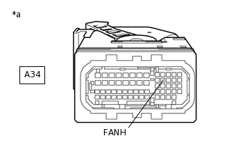
*a
Front view of wire harness connector
(to ECM)
Disconnect the A34 ECM connector.
Turn the ignition switch to ON.
Measure the voltage according to the value(s) in the table below.
Standard Voltage
Tester Connection
Condition
Specified Condition
A34-23 (FANH) - Body ground
Ignition switch ON
11 to 14 V
Reconnect the A34 ECM connector.
Result
Proceed to
OK
NG
NG CHECK HARNESS AND CONNECTOR (FAN NO. 1 RELAY - ECM)Click here
-
CHECK TERMINAL VOLTAGE (FAN NO. 1 RELAY)
-
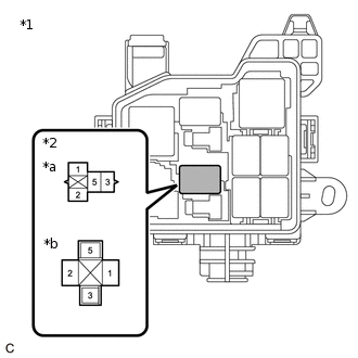
*1
No. 2 Engine Room Relay Block
*2
FAN NO. 1 Relay
*a
Normal Spec
*b
Tropic Spec
Remove the FAN NO. 1 relay from the No. 2 engine room relay block.
Measure the voltage according to the value(s) in the table below.
Standard Voltage
Tester Connection
Condition
Specified Condition
3 (FAN NO. 1 relay) - Body ground
Always
11 to 14 V
Reinstall the FAN NO. 1 relay.
Result
Proceed to
OK
NG
NG REPAIR OR REPLACE HARNESS OR CONNECTOR (FAN NO. 1 RELAY - BATTERY)
-
CHECK HARNESS AND CONNECTOR (FAN NO. 1 RELAY - COOLING FAN MOTOR)
Remove the FAN NO. 1 relay from the No. 2 engine room relay block.
Disconnect the A48 cooling fan motor connector.
Measure the resistance according to the value(s) in the table below.
Standard Resistance
Tester Connection
Condition
Specified Condition
5 (FAN NO. 1 relay) - A48-2
Always
Below 1 Ω
5 (FAN NO. 1 relay) or A48-2 - Body ground
Always
10 kΩ or higher
Reconnect the A48 cooling fan motor connector.
Reinstall the FAN NO. 1 relay.
Result
Proceed to
OK
NG
NG REPAIR OR REPLACE HARNESS OR CONNECTOR
CHECK HARNESS AND CONNECTOR (COOLING FAN MOTOR - BODY GROUND)
Disconnect the A48 cooling fan motor connector.
Measure the resistance according to the value(s) in the table below.
Standard Resistance
Tester Connection
Condition
Specified Condition
A48-1 - Body ground
Always
Below 1 Ω
Reconnect the A48 cooling fan motor connector.
Result
Proceed to
OK
NG
NG REPAIR OR REPLACE HARNESS OR CONNECTOR
INSPECT FAN NO. 1 RELAY
Inspect the FAN NO. 1 relay.
Result
Proceed to
OK
NG
NG REPLACE FAN NO. 1 RELAY
CHECK HARNESS AND CONNECTOR (FAN NO. 1 RELAY - ECM)
Remove the FAN NO. 1 relay from the No. 2 engine room relay block.
Disconnect the A34 ECM connector.
Measure the resistance according to the value(s) in the table below.
Standard Resistance
Tester Connection
Condition
Specified Condition
1 (FAN NO. 1 relay) - A34-23 (FANH)
Always
Below 1 Ω
1 (FAN NO. 1 relay) or A34-23 (FANH) - Body ground
Always
10 kΩ or higher
Reconnect the A34 ECM connector.
Reinstall the FAN NO. 1 relay.
Result
Proceed to
OK
NG
NG REPAIR OR REPLACE HARNESS OR CONNECTOR
INSPECT FAN NO. 1 RELAY
Inspect the FAN NO. 1 relay.
Result
Result
Proceed to
OK (w/ Entry and Start System)
A
OK (w/o Entry and Start System)
B
NG
C
B CHECK HARNESS AND CONNECTOR (FAN NO. 1 RELAY - IGNITION OR STARTER SWITCH ASSEMBLY)Click here
C REPLACE FAN NO. 1 RELAY
CHECK HARNESS AND CONNECTOR (FAN NO. 1 RELAY - IG1 RELAY)
Remove the FAN NO. 1 relay from the No. 2 engine room relay block.
Remove the IG1 relay from the center relay block.
Measure the resistance according to the value(s) in the table below.
Standard Resistance
Tester Connection
Condition
Specified Condition
2 (FAN NO. 1 relay) - 5 (IG1 relay)
Always
Below 1 Ω
2 (FAN NO. 1 relay) or 5 (IG1 relay) - Body ground
Always
10 kΩ or higher
Reinstall the IG1 relay.
Reinstall the FAN NO. 1 relay.
Result
Proceed to
OK
NG
NG REPAIR OR REPLACE HARNESS OR CONNECTOR
CHECK HARNESS AND CONNECTOR (FAN NO. 1 RELAY - ECM)
Remove the FAN NO. 1 relay from the No. 2 engine room relay block.
Disconnect the A34 ECM connector.
Measure the resistance according to the value(s) in the table below.
Standard Resistance
Tester Connection
Condition
Specified Condition
1 (FAN NO. 1 relay) or A34-23 (FANH) - Body ground
Always
10 kΩ or higher
Reconnect the A34 ECM connector.
Reinstall the FAN NO. 1 relay.
Result
Proceed to
OK
NG
NG REPAIR OR REPLACE HARNESS OR CONNECTOR
CHECK HARNESS AND CONNECTOR (FAN NO. 1 RELAY - IGNITION OR STARTER SWITCH ASSEMBLY)
Remove the FAN NO. 1 relay from the No. 2 engine room relay block.
Disconnect the E21 ignition or starter switch assembly connector.
Measure the resistance according to the value(s) in the table below.
Standard Resistance
Tester Connection
Condition
Specified Condition
2 (FAN NO. 1 relay) - E21-1 (IG1)
Always
Below 1 Ω
2 (FAN NO. 1 relay) or E21-1 (IG1) - Body ground
Always
10 kΩ or higher
Reconnect the E21 ignition or starter switch assembly connector.
Reinstall the FAN NO. 1 relay.
Result
Proceed to
OK
NG
NG REPAIR OR REPLACE HARNESS OR CONNECTOR
INSPECT IGNITION OR STARTER SWITCH ASSEMBLY
Inspect the ignition or starter switch assembly.
Result
Proceed to
OK
NG
OK REPAIR OR REPLACE HARNESS OR CONNECTOR (BATTERY - IGNITION OR STARTER SWITCH ASSEMBLY)