CYLINDER HEAD REASSEMBLY
PROCEDURE
INSTALL CYLINDER HEAD STUD BOLT
Tip:If a cylinder head stud bolt is deformed or the threads are damaged, replace it.
Using an E8 "TORX" socket wrench, install the cylinder head stud bolts.
for stud bolt A and B
12 N*m
122 kgf*cm
9 ft.*lbf
for stud bolt C
8.0 N*m
82 kgf*cm
71 in.*lbf
Using an E6 "TORX" socket wrench, install the cylinder head stud bolt.
for stud bolt D
5.0 N*m
51 kgf*cm
44 in.*lbf
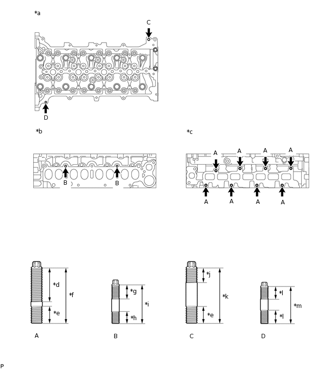
*a
Cylinder Head Cover Side
*b
Intake Manifold Side
*c
Exhaust Manifold Side
*d
40 mm (1.57 in.)
*e
15 mm (0.591 in.)
*f
58.5 mm (2.30 in.)
*g
20 mm (0.787 in.)
*h
13 mm (0.512 in.)
*i
35 mm (1.38 in.)
*j
14 mm (0.551 in.)
*k
47 mm (1.85 in.)
*l
12 mm (0.472 in.)
*m
37 mm (1.45 in.)
-
-
INSTALL NO. 1 STRAIGHT SCREW PLUG WITH HEAD
Apply adhesive to the No. 1 straight screw plugs.
Adhesive
Toyota Genuine Adhesive 1324, Three Bond 1324 or equivalent
Using a 6 mm hexagon wrench, install the 4 No. 1 straight screw plugs.
25 N*m
255 kgf*cm
18 ft.*lbf
INSTALL NO. 1 WATER BY-PASS PIPE
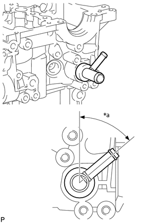
*a
45 to 55°
Tip:When using a new cylinder head sub-assembly, a No. 1 water by-pass pipe must be installed.
Apply adhesive to a new No. 1 water by-pass pipe so that it covers the entire circumference of the part which contacts the hole of the cylinder head sub-assembly.
Adhesive
Toyota Genuine Adhesive 1324, Three Bond 1324 or equivalent
Install the No. 1 water by-pass pipe as shown in the illustration.
INSTALL WATER OUTLET
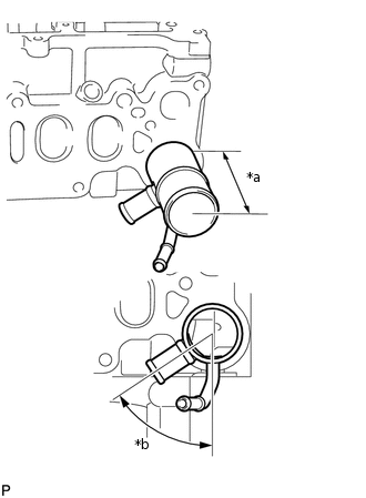
*a
79 to 85 mm
*b
51 to 61°
Tip:When using a new cylinder head sub-assembly, a water outlet must be installed.
Apply adhesive to a new water outlet so that it covers the entire circumference of the part which contacts the hole of the cylinder head sub-assembly.
Adhesive
Toyota Genuine Adhesive 1324, Three Bond 1324 or equivalent
Install the water outlet.
Standard protrusion
79 to 85 mm (3.11 to 3.35 in.)
Standard angle
51 to 61°
INSTALL ELBOW
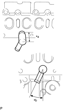
*a
56.5 to 62.5 mm
*b
20 to 30°
Tip:When using a new cylinder head sub-assembly, an elbow must be installed.
Apply adhesive to a new elbow so that it covers the entire circumference of the part which contacts the hole of the cylinder head sub-assembly.
Adhesive
Toyota Genuine Adhesive 1324, Three Bond 1324 or equivalent
Install the elbow.
Standard protrusion
56.5 to 62.5 mm (2.22 to 2.46 in.)
Standard angle
20 to 30°
INSTALL VALVE SPRING SEAT
Install the valve spring seats to the cylinder head sub-assembly.
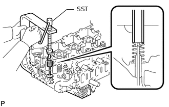
INSTALL VALVE STEM OIL SEAL
Apply a light coat of engine oil to a new valve stem oil seal.
-
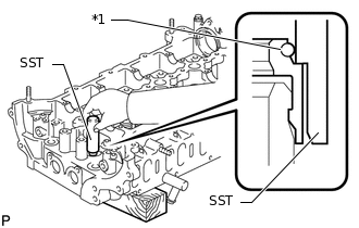
*1
Valve Stem Oil Seal
Using SST, push in the valve stem oil seal.
09201-41020
Note:Failure to use SST will cause the valve stem oil seal to be damaged or improperly seated.
INSTALL INTAKE VALVE
-
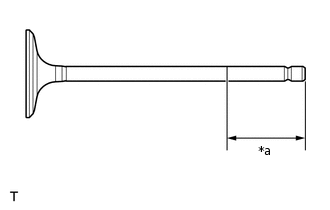
*a
50 mm (1.97 in.)
Apply plenty of engine oil to the tip area of the intake valve shown in the illustration.
Place the cylinder head sub-assembly on a wooden block.
Install the intake valve, inner compression spring and valve spring retainer to the cylinder head sub-assembly.
Note:Install the same parts in the same combination to their original locations.
-
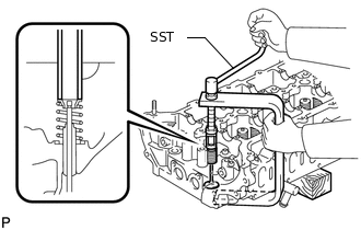
Using SST, compress the inner compression spring and place the valve spring retainer lock around the intake valve stem.
09202-70020
Using a 5 mm pin punch and plastic-faced hammer, lightly tap the intake valve stem tip to ensure a proper fit.
Note:Be careful not to damage the intake valve stem tip.
-
INSTALL EXHAUST VALVE
-
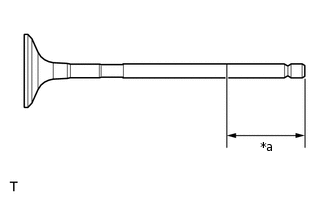
*a
50 mm (1.97 in.)
Apply plenty of engine oil to the tip area of the exhaust valve shown in the illustration.
Place the cylinder head sub-assembly on a wooden block.
Install the exhaust valve, inner compression spring and valve spring retainer to the cylinder head sub-assembly.
Note:Install the same parts in the same combination to their original locations.
-
Using SST, compress the inner compression spring and place the valve spring retainer lock around the exhaust valve stem.
09202-70020
Using a 5 mm pin punch and plastic-faced hammer, lightly tap the exhaust valve stem tip to ensure a proper fit.
Note:Be careful not to damage the exhaust valve stem tip.
-